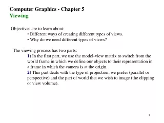
Interactive Computer Graphics Viewing Principles
Learn about classical and perspective viewing techniques, camera positioning, and projection matrices for interactive computer graphics. Explore parallel and perspective projections, transformation pipelines, and camera positioning concepts.

Interactive Computer Graphics Viewing Principles
E N D
Presentation Transcript
Interactive Computer GraphicsViewing James Gain and Edwin Blake Department of Computer ScienceUniversity of Cape Town July 2002jgain@cs.uct.ac.za Collaborative Visual Computing Laboratory
Map of the Lecture • Classical Viewing: • Orthographic, Axonometric, Oblique, Perspective • Camera Positioning and Viewing APIs • Simple Projection Matrices • Implementing Projections in OpenGL • Projections and Shadows Transformations Viewing Shading Interactive Computer Graphics Contents
Viewing Principles • Image formed by intersection of projection plane and lines of projection from object to viewer • Perspective Viewing: • Projectors converge to a finite Centre of Projection (COP) • Objects in the distance are shrunk • Parallel Viewing: • As COP is moved to infinity, projectors become parallel • Projectors oriented along a Direction of Projection (DOP) • Preserves relative lengths and angles Perspective Projection Parallel Projection Interactive Computer Graphics Contents
Classical Viewing: Parallel I • Unlike CG, Classical viewing depends on a specific relationship between object and viewer • Many objects (e.g. buildings) have a box-like shape with 6 principal faces oriented relative to the projection plane • Orthographic: • projection plane is parallel to a single principal face • Preserves both distance and angles • But usually need multiple projections because only on face visible at a time Interactive Computer Graphics Contents
Classical Viewing: Parallel II • Axonometric: • Projectors are orthogonal to projection plane • Angles are no longer preserved • Isometric: three principal faces symmetric with respect to the plane • Dimetric: two prinicipal faces symmetric with respect to plane • Trimetric: general case • Oblique: • Projectors are parallel to each other but make an arbitrary angle with the projection plane • Not physically realistic Interactive Computer Graphics Contents
Classical Viewing: Perspective • Characterized by diminution • Distortion is non-linear: • Unable to take measurements • But more realistic • Categorised according to number of visible faces and consequent number of vanishing points for principal directions • All classical views are simply a subset of either general parallel or perspective CG viewing Three-point Two-Point One-Point Interactive Computer Graphics Contents
Transformation Pipeline Modelling Transform Object in object co-ordinates Object in world co-ordinates Viewing Transform Object in 2D screen co-ordinates Perspective Projection Object in viewing co-ordinates Interactive Computer Graphics Contents
Positioning of the Camera • The viewpoint (camera) is located at the origin and the projection plane is parallel to the plane at a distance along the negative axis • Camera Transformation: • Must be able to position and orient the camera arbitrarily • Transform objects from modelling coordinates to camera coordinates • Need an appropriate way of specifying the camera position and orientation • OpenGL: • Camera has a left-hand coordinate system • Camera transformation is part of the GL_MODELVIEW state Interactive Computer Graphics Contents
u-v-n Viewing • Create a camera frame (point and 3 orthonormal vectors): • Positioned at a view-reference point (VRP) • Viewing pointed along the view- plane normal ( ). Determines the orientation of the viewplane • Viewing oriented by the view-up vector (VUP). Sets the roll of the viewplane • Construct a camera frame • = Projection of VUP onto plane • = Normalizaion of Interactive Computer Graphics Contents
Look-At Viewing • Camera located at an eyepoint (eye) specified in world coordinates, pointed towards an atpoint (at) with a view-up vector (up) • gluLookAt(eyex, eyey, eyez, atx, aty, atz, upi, upj, upk); • Alters the modelview matrix to match this camera transform Interactive Computer Graphics Contents
Euler and Polar Viewing • Other applications require a non-rectilinear coordinate system • Flight Simulation: • Three Euler angles (roll, pitch and yaw) relative to a vehicle’s centre of mass • Stellar Cartography: • Polar coordinates (azimuth, elevation and distance) relative to a ground plane and position Interactive Computer Graphics Contents
Perspective Projection • From 3D world co-ordinates to 2D screen co-ordinates • Perspective projection provides an illusion of depth in an image by giving distant objects a smaller projected screen size • The screen co-ordinates of a point are calculated using similar triangles Interactive Computer Graphics Contents
Geometry of Perspective Projection • Triangle is similar to . • Similarly: • The Projection Transform is: Interactive Computer Graphics Contents
Exercise: Binocular Projection • Calculate the separate screen projections and for the left and right eyes of a point . The eyes are located at and Interactive Computer Graphics Contents
Solution: Binocular Projection • Right eye: • Triangle is similar to . • Left eye: • By a similar derivation • The co-ordinate projection is unchanged because our eyes are only separated horizontally. Interactive Computer Graphics Contents
Orthogonal Projection • Projectors are perpendicular to the viewplane • Points retain their and values: Interactive Computer Graphics Contents
Projections in OpenGL • Need to consider focal length and size of the film plane • View Volume: • Determines the field of view for clipping objects • A truncated pyramid (frustum) with apex at the COP • Specified by front and back clipping planes and a horizontal and vertical angle of view Interactive Computer Graphics Contents
Perspective Viewing in OpenGL • glFrustum(xmin, xmax, ymin, ymax, near, far); • near and far must both be positive. Note: they are specified in camera coordinates, so • gluPerspective(fovy, aspect, near, far); • fovy is the angle between the top and bottom frustum planes, aspect = width / height • Must make sure to first select the GL_PROJECTION matrix mode: • glMatrixMode(GL_PROJECTION); Interactive Computer Graphics Contents
Parallel Viewing in OpenGL • glOrtho(xmin, xmax, ymin, ymax, near, far); • Again • But near and far are not restricted to being positive Interactive Computer Graphics Contents
Hidden Surface Removal • Opaque surfaces cause occlusion • Use Hidden-Surface Removal to delete invisible surfaces • Z-buffer algorithm: • As polygons are rasterized store depth value of projected points. Only render a point with current minimum depth • Worst-case complexity equals number of polygons • Need specialized memory - depth or z buffer • Amenable to hardware implementation z-buffer Algorithm • OpenGL z-buffer: • glutInitDisplayMode(GLUT_DEPTH); initialize z-buffer in display • glEnable(GL_DEPTH_TEST); enable hidden surface removal • glClear(GL_DEPTH_BUFFER_BIT); clear z-buffer before rendering Interactive Computer Graphics Contents
Projection Normalization • Projection Requirements: • Handle general view volumes • Retain depth information (required by HSR) as far down the pipeline as possible • Projection Solution: • Decompose projection into a distortion and canonical orthographic projection • Canonical View Volume glOrtho(-1.0, 1.0, -1.0, 1.0, -1.0, 1.0); Perspective Projection = Distortion and Orthographic projection Interactive Computer Graphics Contents
Orthogonal Projection • glOrtho(xmin, xmax, ymin, ymax, near, far) • glOrtho(-1.0, 1.0, -1.0, 1.0, -1.0, 1.0) • Translate: • Centre of view volume to origin • Scale: • View volume to cube with sides of length 2 Interactive Computer Graphics Contents
Perspective Normalization • Convert perspective view frustrum to orthographic cube • gluPerspective(90.0, 1.0, zmin, zmax) • glOrtho(-1.0, 1.0, -1.0, 1.0, -1.0, 1.0) • Near plane at zmin, far plane at zmax, fovy = 90 deg, aspect = square • Mapping is non-linear but preserves the ordering of depth Interactive Computer Graphics Contents
Projection and Shadows • Shadows are useful shape cues • Fully general shadowing algorithms are expensive • But simple shadows (from a point light source onto a flat plane) can be simulated with projection • Set COP to light source, apply perspective transform to polygon in front of projection plane to create shadow polygon • Example: • Light source • Shadow projection onto • Exercise: Write out Interactive Computer Graphics Contents