Download
1 / 20
200 likes | 225 Vues
Explore mechanisms of heat extraction, thermal configurations, insulation barriers, and innovative techniques in superconducting magnet design. Learn from experts in Paris.

E N D
Thermomag-07 A CARE-HHH workshop on Heat Generation and Transfer in Superconducting Magnet 19-21 November 2007, Paris Mechanisms of heat extraction through cable insulation B. Baudouy CEA/Saclay - Dapnia/SACM
Outline • The temperature margin and thermal configuration • The electrical insulation • The heat paths • Heat transfer through the small face • Heat transfer through the coil • NED Ceramic insulation result • NED conventional insulation result
Temperature margin and thermal configuration • “Wet” magnets with internal “cooling source” • Large internal losses and smaller stored energy • Single phase coolant in contact with conductor • Cooling Source: Internal tube flow heat exchanger • Heat dissipated in the conductors • Beam losses for LHC 10 mW/cm3 or 0.4 W/m • 3D configuration but can be reduced to 2D • Heat transfer between the conductor and the cooling source determines the temperature margin • HT from cooling source to the coil through collars … • HT in the coil from the conductor to surrounding coolant through the electrical insulation and the cable itself • Electrical insulation constitutes the largest thermal barrier • For LHC magnet • May not be the case for all accelerator magnet
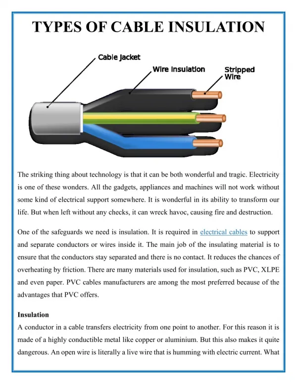
Electrical insulation • Historical insulation : 2 wrappings • First wrapping in polyimide with 50% overlap • Second wrapping in epoxy resin-impregnated fiberglass with gap • The LHC insulation work : 2 wrappings • First wrapping in polyimide with 50% overlap • Second wrapping in polyimide with polyimide glue with gap • Current LHC Insulation : 3 wrappings • First 2 wrappings with no overlap • Last wrapping with a gap • Innovative insulation for Nb3Sn magnet • First wrapping 50% Courtesy of F. Rondeaux (CEA) Baudouy [1], Meuris[2] and Puigsegur [3]
Open Channels Channels between insulation The heat paths (1/2) • Heat transfer configuration • Volume dissipation in the conductors • Collars side is thermally insulated • Heat flux goes through the 1st layer and 2nd layer • Heat flux has to go through the cable • Conductor • Insulation • Heat paths to be considered • Small face path • Large face path
The heat paths (2/2) Conductors Small face :Transverse HT through the insulation second layer Insulation First layer Large face : Transverse HT through the insulation and longitudinal HT in the “channels” between conductor insulation • Transverse HT through insulation • Experimental model : Drum • He II + conduction // model • “Channels” HT not known • Overall heat transfer in the coil • Experimental model: Stack (CEA, KEK) • Network channel model
second layer First layer Heat transfer through the small face (1/3) • Heat transfer through the small face : the drum experiment • Experimental study the transverse heat transfer • Real insulation • No mechanical constraints Baudouy [1], [4]
Heat transfer through the small face (2/3) • Small heat flux : Landau regime • Transition from Landau to GM regime • High heat flux : Gorter-Mellink regime • Higher heat flux : Conduction + He II Baudouy [1], [4]
Heat transfer through the small face (3/3) • Conduction + He II (GM) regime Baudouy [1], [4]
Heat transfer in the coil : The stacks (1/3) • Saclay’s Stack • Stack of five insulated conductors under mechanical constraint • Conductor in stainless steel heated by Joule effect • Polymerization under 50 to 150 MPa at 130°C to 170°C • No helium in the conductor Baudouy [1] and Meuris [2] Real cable Stainless steel cable Thermometers
Heat transfer in the coil : The stacks (2/3) • KEK Stack • Stack of six insulated conductors under mechanical constraint • Conductor in Cu-Ni(10%) strands Ø 0.8 mm (w=11 mm x h=1.5 mm) • Helium in the conductor Courtesy of N. Kimura (KEK) Kimura [5]
Heat transfer in the coil : The stacks (3/3) Richter [6] • CERN “Stack” = Piece of LHC coil • Heat in the sample is generated by DC currents flowing through resistive inter-strand contacts Courtesy of D. Richter (CERN)
Heat transfer in the coil : Results (2/4) • Epoxy Resin fills up the helium path • Dry fiber thermally decouples the conductors • Small paths of helium for polyimide insulations with gaps due to over lapping LHC SSC Increasing permeability Meuris[2]
Heat transfer in the coil : Results (3/4) • Artificial permeability with 6 holes of Φ 200 µBaudouy [1] • Holes reduce permeability and Rth of small face and of the insulation • Small ∆T, heat transfer through the holes • High ∆T, heat transfer through holes and conduction
Heat transfer in the coil : Results (4/4) • Test with a “Saclay stack” and Central conductor heated • Insulation all polyimide (Kapton) A34bis • 1st layer : Kapton 200 HN 50 μm x 11 mm 2 wrappings (no overlap) • 2nd layer Kapton 270 LCI 71 μ m x 11 mm 2 mm gap Richter [6] • High Ramp Rate Quench measurement at CERN versus Saclay stacks results • For T>Tλ, MagnetCERN=0.5 Stack • Outer layer blocked
Heat transfer in the coil : Models • Saclay numerical model : Conduction and He II • KEK physical model : Only He II Meuris [2] Kimura [5]
NED : Innovative insulation • One wrapping with 50% overlap • Heat treatment of 100 h at 660 °C • 10 MPa compression only ! • 5 conductors heated LHC SSC Baudouy [8] Increasing permeability Courtesy of F. Rondeaux (CEA) ΔT=5 mK @ 150 mW through 5 conductors
Glass-fibre epoxy insulation developed by RAL Determination of λ and Kapitza resistance Λ 4 times lower than kapton Rkapitza identical NED : Conventional insulation Canfer [7] NED conventional insulation LHC SSC Increasing permeability NED Ceramic insulation Baudouy [8] ΔT=5 mK @ 150 mW through 5 conductors
References [1] Baudouy B, Ph D Thesis, Univ. Paris VI, 1996 [2] Meuris C, Baudouy B, Leroy D, and Szeless B. Heat transfer in electrical insulation of LHC cables cooled with superfluid helium. Cryogenics 1999; 39: 921-931. [3] A. Puigsegur, F. Rondeaux, E. Prouzet, and K. Samoogabalan, Development of an innovative insulation for Nb3Sn wind and react coils, Adv. Cryo. Eng. (Materials)50A, AIP, Ed. U. Balachandran, (2004) 266-272 [4] Baudouy B, François MX, Juster F-P, and Meuris C. He II heat transfer through superconducting cables electrical insulation. Cryogenics 2000; 40: 127-136. [5] Kimura N, Yamamoto A, Shintomi T, Terashima A, Kovachev V, and Murakami M. Heat transfer characteristics of Rutherford-type superconducting cables in pressurized He II. Ieee Transactions on Applied Superconductivity 1999; 9: 1097-1100. [6] David Richter, Jerôme Fleiter, Bertrand Baudouy, Arnaud Devred, “Evaluation of the Transfer of Heat from the Coil of the LHC Dipole Magnet to Helium II”, IEEE Trans. on Applied Superconductivity (2007), 17 n°2, p. 1263-1268 [7] S. Canfer et al , “Insulation Development for the Next European Dipole”,MT20, Philadelphia, USA, 2007 • [8] B. Baudouy, J. Polinski, CARE NED Work Package 2 “Thermal Studies and Quench Protection” - Final report on Heat transfer study, Nov. 2007.