Download
1 / 6
60 likes | 187 Vues
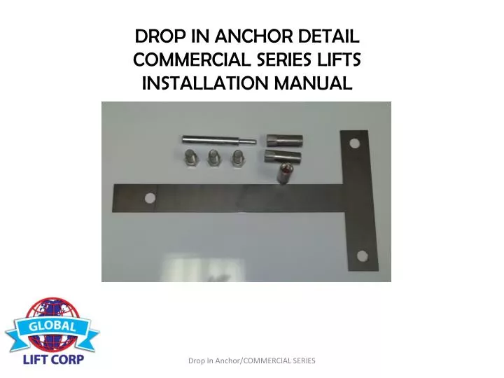
DROP IN ANCHOR DETAIL COMMERCIAL SERIES LIFTS INSTALLATION MANUAL. DROP IN ANCHORING SYSTEM COMMERCIAL SERIES LIFTS. PACKING LIST 3 – Drop In Anchor’s 3 – ¾”x 1” Bolts 1 – T – Shaped Template 3 – Black Caps.

E N D
DROP IN ANCHOR DETAIL COMMERCIAL SERIES LIFTS INSTALLATION MANUAL Drop In Anchor/COMMERCIAL SERIES
DROP IN ANCHORING SYSTEM COMMERCIAL SERIES LIFTS • PACKING LIST • 3 – Drop In Anchor’s • 3 – ¾”x 1” Bolts • 1 – T – Shaped Template • 3 – Black Caps Drop In Anchor/COMMERCIAL SERIES
ADA GUIDELINES FOR POOL LIFT PLACEMENT • Pool Lift Location. Pool lifts shall be located where the water level does not exceed 48 inches (1220 mm). • Seat Location. In the raised position, the centerline of the seat shall be located over the deck and 16 inches (405 mm) • minimum from the edge of the pool. The deck surface between the centerline of the seat and the pool edge shall have a • slope not steeper than 1:48. • Clear Deck Space. On the side of the seat opposite the water, a clear deck space shall be provided parallel with the seat. • The space shall be 36 inches (915 mm) wide minimum and shall extend forward 48 inches (1220 mm) minimum from a line located • 12 inches (305 mm) behind the rear edge of the seat. The clear deck space shall have a slope not steeper than 1:48. • Submerged Depth. The lift shall be designed so that the seat will submerge to a water depth of 18 inches (455 mm) minimum • below the stationary water level. To make sure the lift has enough clearance the lift should be installed at a location • with 44”-48” of Water depth Drop In Anchor/COMMERCIAL SERIES
Distance must be 19” From pool’s edge Front Holes Hole’s parallel with pool’s edge • STEP 1: Locate the Drop In anchoring system template (included and shown above) • Once you determine where your lift is going to be located place the template down • So you can mark on the concrete where you will need to drill the holes. • The dimensions are as follows: The front holes (centerline) must be 19” • From the pools edge. Also make sure that the front holes are parallel to the pools edge. Drop In Anchor/COMMERCIAL SERIES
15.00 8.00 15.00 • Step 2: You will need a 7/8” rock carbide drilling bit. • Make sure you have accurately marked your hole location to be drilled. After drilling • Your holes they must be 2 1/2” deep. Double check your measurements they should be: • Front holes 8” from centerline from hole to hole (see above). The measurement from front • to back should be 15” from Centerline of each hole (see above). Clean hole with pressurized • Air or a vacuum. Drop In Anchor/COMMERCIAL SERIES
Picture A Picture B • STEP 3: • Drive the anchor flush with the surface of concrete (shown in picture A) • Expand the anchor with the setting tool (provided). Anchor is properly • expanded when shoulder of the setting tool is flush with the top of • the anchor (shown in picture B). Now you are ready to install your Commercial • Series Lift. Drop In Anchor/COMMERCIAL SERIES