Download
1 / 47
470 likes | 505 Vues
Research & Development activities at SCIPP focuses on physics studies, detector resolution standards, silicon tracking, and proof-of-principle hardware development. Explore selectron production, SiD tracking capabilities, and detector noise simulation.

E N D
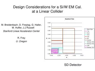
SCIPP R&D on the International Linear Collider Detector SCIPP Review November 29, 2005 Presenter: Bruce Schumm
R&D Activity is increasing, with studies now on four fronts: • Physics and machine studies for e-e- running • Detector resolution standards from physics simulation • Reconstruction capabilities of all-silicon tracking • Hardware proof-of-principle of low-mass silicon tracking Current involvements (all very much part time) 3 senior physicists, 1 post-doc (looking for a second), 4 undergraduate thesis students, 1 Engineer, 2 technical staff, one bored spouse of a Silicon Valley engineer.
International Linear Collider: Activity on the e-e- Front • Clem Heusch is the SCIPP participant in e-e- studies • Leading international effort in the use and application of e-e- beams at the ILC • Continuing series of workshops hosted by SCIPP; proceedings published in World Scientific • Heusch is a member of ILC Subcommittee on International Collaboration.
Detector Resolution Standards from Selectron Production Participants: Senior Physicist Bruce Schumm Undergraduate Thesis Students Sharon Gerbode, Heath Holguin, Troy Lau*, Paul Moser, Adam Perlstein, Joseph Rose, Matthew Vegas Community Member (on hold before Grad School) Ayelet Lorberbaum *Recipient of two Undergraduate Research Awards; grad school at U. Michigan.
Original Motivation To explore the effects of limited detector resolution on our ability to measure SUSY parameters in the forward (|cos()| > .8) region. SiD Tracker
SPS 1 Spectroscopy: At Ecm = 1Tev, selectrons and neutralino are light. selectrons • Beam/Brehm: • √smin=1 • √smax=1000 • = .29 sz = .11 (mm) LSP
Electron energy distribution with beam/bremm/ISR (.16%). No detector effects or beam energy spread. Upper Endpoint Lower Endpoint • sample electron energy distribution Mselectron = 143.112 (SPS1A)
Selectrons vs. cos() SPS1A at 1 TeV Roughly ½ of statistics above |cos()| of 0.8, but… Electrons vs. cos()
The spectrum is weighted towards higher energy at high |cos()|, so there’s more information in the forward region than one might expect.
Determine the selectron mass accuracy in both the central (0 < |cos| < 1) and full (0 < |cos| < 1) region
Ongoing work: Fitting simulaneously for selectron and gaugino (0) masses at Ecm = 500 GeV This is an ILC Physics benchmark process (Lorberbaum, Schumm, Vegas)
Simulation of SiD Tracking System (and SiD variants) Participants: Senior Physicist Bruce Schumm Recent Graduate Students Christian Flacco, Michael Young* Undergraduate Thesis Student Eric Wallace *Supported primarily through department (TA) funds; SLAC paid for ½ of his support this summer.
Simulation of SiD Tracking System, continued Three areas of work: Fast MC Simulation Billior-based LCDTRK.f (B. Schumm) provides covariance matrices for fast MC simulation and resolution plots. Pulse Development Simulation Provides simulation of pulse development and amplification. Will soon be incorporated in international simulation framework (awaiting “hook” from Norman Graf at SLAC) SiD Tracking Capabilities Explore tracking performance of SiD tracker and variants
LCDTRK.f comparison of SiD options with TESLA (LDC) design, from Snowmass 2005
Pulse Development Simulation Long Shaping-Time Limit: strip sees signal if and only if hole is col- lected onto strip (no electrostatic coupling to neighboring strips) Charge Deposition:Landau distribution (SSSimSide; Gerry Lynch LBNL) in ~20 independent layers through thickness of device Geometry:Variable strip pitch, sensor thickness, orientation (2 dimen- sions) and track impact parameter Lorentz Angle:18 mrad per Tesla (holes), from measurements
Carrier Diffusion Hole diffusion distribution given by Offest t0 reflects instantaneous expansion of hole cloud due to space-charge repulsion. Diffusion constant given by mh = hole mobility Reference: E. Belau et al., NIM 214, p253 (1983)
Electronics Simulation Detector Noise: From SPICE simulation, normalized to bench tests with GLAST electronics Analog Measurement: Employs time-over-threshold with variable clock speed; lookup table provides conversions back into analog pulse height (as for actual data) RMS Gaussian Fit Essential tool for design of front-end ASIC Detector Resolution (units of 10m)
Non-normal incidence Also need to understand performance as a function of various parameters, e.g., angle at entrance to the detector (identify issues for test-beam running)
Pattern Recognition Capabilities of an All-Silicon Central Tracker Can one do pattern recognition with only five central tracking layers? Might more layers improve performance to an extent that justifies the extra material? SiD Tracker Current code: Nick Sinev, U. Oregon
EVENT/TRACK SELECTION • Choose qqbar events at Ecm= 500 GeV (dense jet cores); Pan/Pythia and GEANT4 generation • Choose events/tracks that should be easily recon-structed (tracks curl up below p= 1 GeV): • Event Selection • |costhrust| < 0.5 • Thrust Mag > 0.94 Track Selection • |costrack| < 0.5 • p > 5 GeV/c
EFFICIENCIES FOR QQBAR EVENTS Doesn’t look that spectacular; what might be going on here?
Of course! The requirement of a VXD stub means that you miss anything that originates beyond r ~ 3cm. This is about 5% of all tracks. With VXDBasedReco, we won’t see a difference between 5 and 8 layer tracking.
TRACK PARAMETER PERFORMANCE • Compare width of Gaussian fit to residuals with two different estimates: • Error from square root of appropriate diagonal error matrix element • Error from Billior calculation (LCDTRK program) • Only tracks with all DOF (5 VTX and 5 CT layers) are considered. • Only gaussian smearing is used, since this is what is assumed for the two estimators. • Qqbar sample extends out to ~100 GeV; use +- sample to get higher energy (200-250 GeV) bin.
CURVATURE ERROR vs. CURVATURE Standard (Original) Code
CURVATURE ERROR vs. CURVATURE “NEW” CODE WITH MODIFIED FITTER
RESULTS FOR (LOWEST BIN) Residuals (Gaussian smear): = 3.40x10⁻⁷ Error Matrix: = 3.12x10⁻⁷ LCDTRK: = 3.26x10⁻⁷ Actual momentum resolution is about 9% worse than LCDTRK expectation Residuals (realistic CCD): = 3.29x10⁻⁷ Apparently, “realistic” CCD resolution is better than assumed value of 5m
Simulation Study Goals • Getting close to ramped-up again with senior thesis student Eric Wallace. • Port our code into new simulation framework (making forward progress!) • Incorporate realistic pulse-development simulation (reconstruction efficiency in jet core) when ready • Validate “ported” version of code. • Combine with new stand-alone central tracker code (Tim Nelson, SLAC) and optimize. • Explore different tracker configurations (8 layers).
The SCIPP/UCSC ILC HARDWARE GROUP Faculty/Senior Alex Grillo Hartmut Sadrozinski Bruce Schumm Abe Seiden Students Michael Young Kunal Arya (Com- puter Eng. Post-Docs [Gavin Nesom*] Jurgen Kroseberg Lead Engineer: Ned Spencer Technical Staff: Max Wilder, Forest Martinez-McKinney *Recently lured away by the sirens of Silicon Valley
The Gossamer Tracker • Ideas: • Low noise readout Long ladders substantially limit electronics readout and support (alternatively, improved res-olution for shorter ladders) • Thin inner detector layers • Exploit duty cycle eliminate need for active cooling Competitive with gaseous track- ing over full range of momenta Also: forward region…
THE LSTFE-2 CHIP Long shaping-time front end suppresses 1/f noise, allowing for long-ladder readout Power cycling should reduce IR heating by close to x100 Analog measurement via time-over-threshold (TOT) from low-threshold “readout” comparator. Redesigned relative to LSTFE-1 to accommodate long pulse train and exploit more relaxed (5 Hz) duty cycle. Submitted to TSMC 0.25m mixed-signal RF process; received August 11 (5 weeks late)
3 s shaping time; analog readout it Time-Over-Thres-hold with 400 nsec clock
128 mip 1 mip Operating point threshold Readout threshold 1/4 mip
RMS RMS Gaussian Fit Gaussian Fit SIMULATED PERFORMANCE FOR 167cm LADDER Resolution as a function of low threshold Efficiency and Occupancy as a function of high threshold
INITIAL RESULTS Expected analog gain of 140 mV/fC confirmed Transition to log-arithmic response (TOT) at ~ 1.5 mip 1 mip
DIGITAL ARCHITECTURE: FPGA DEVELOPMENT Digital logic should perform basic zero suppression (intrinsic data rate for entire tracker would be approximately 50 GHz), but must retain nearest-neighbor information for accurate centroid.
Status of Back-End Architecture Development • First-pass digital strategy worked out • FPGA code developed for 8-channel system • Simulated data stream (including noise and detector background) injected and processed in simulation • Data rates estimated
Li Hi Li+1 Hi+1 Li+2 Hi+2 Li+3 Hi+3 Li+4 Hi+4 Li+5 Hi+5 Li+6 Hi+6 Proposed LSTFE Back-End Architecture Low Comparator Leading-Edge-Enable Domain 8:1 Multi-plexing (clock = 50 ns) FIFO (Leading and trailing transitions) Event Time Clock Period = 400 nsec
FIFO FIFO FIFO Controller FIFO FIFO FIFO Proposed LSTFE Back-End Architecture (cont’d) Per 128 Channel Chip: 1 Master FIFO reads out 32 local FIFO’s Store in Master FIFO essentially complete by end of ~1ms beam spill Master FIFO
DIGITAL ARCHITECTURE VERIFICATION ModelSim package permits realistic simulation of FPGA code (for now, up to signal propagation delay) Simulate detector background and noise rates for 500 GeV running, as a function of read-out threshold. Per 128 channel chip ~ 7 kbit per spill 35 kbit/second For entire long shaping-time tracker ~ 0.5 GHz data rate (x100 data rate suppression) Nominal Readout Threshold
HARDWARE SUMMARY • Progress on key fronts: • Front-end electronics development • LSTFE-2 chip (cold-rf optimization) designed and testing underway • Digital architecture • Proposed back-end architecture developed and verified; raw data rates acceptable (0.5 GHz) • Ladder construction underway • Substantial work remains in all these areas; working towards testbeam run in late 2006
OVERALL SUMMARY • Linear Collider R&D at SCIPP is: • Directly benefiting from SCIPP expertise • Focused on central issues for the ILC • Supporting leadership roles (international cooperation, oversight of tracking RD) • Creating synergies with other SCIPP programs • Providing key educational opportunities, undergrad through postdoc, with a good placement record