Download
1 / 44
440 likes | 558 Vues
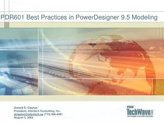
PDR601 Best Practices in PowerDesigner 9.5 Modeling. Donald D. Clayton President, Intertech Consulting, Inc. dclayton@intertech.us (713) 586-6481 August 5, 2003. Objectives. Understand the ways modern systems are becoming increasingly complex

E N D
PDR601 Best Practices in PowerDesigner 9.5 Modeling Donald D. ClaytonPresident, Intertech Consulting, Inc.dclayton@intertech.us (713) 586-6481August 5, 2003
Objectives • Understand the ways modern systems are becoming increasingly complex • Review the differences between traditional client/server practices and three-tier and distributed computing. • Learn practical design techniques for managing this complexity • Understand how to use PowerDesigner and UML to control this complexity
Topics • Modern System Development Architectures • Brief History of UML • UML Views • UML Phases
Modern System Development Architectures • Enterprise systems have increased in sophistication from early days of Client/Server • Today’s business systems need to support a variety of client types • In this environment, it difficult to impossible to “RAD” the application • UML gives us the semantics to support these efforts • PowerDesigner gives us the tool to support these efforts
Distributed Application Development Client Middle Tier Data Web Server Browser Very Thin PageServer ProductionData FileSystem HTML Pages ProductionData Templates, Scripts Browser or C/S Thin TransactionServer ProductionData Components Components ProductionData Enterprise JavaBeans, COM, CORBA, PB NVOs Client/ServerApplication Rich ProductionData Components
So Where Does PowerDesigner Fit In? • The PowerDesigner program can be used by a variety of users with different backgrounds • Business Analysts • Database Administrators • System Programmers • Your role, the point in the systems development process, and the technology set you are using all determinants in using PowerDesigner
Differences Between Model Types • The CDM, PDM, and OOM models are intended for different audiences with different needs • How PowerDesigner is used depends partially on the background and role of the person using it. • Conceptual Data Models • Good for Business Analysts and DBAs • Physical Data Models • Good for DBAs and System Developers • Object-Oriented Models • Good for System Developers and DBAs
Java Code • (Source, Bytecode, JAR) • - PowerBuilder Code Object-Oriented Model (OOM) - Application Structure - Business Logic Java Source PowerBuilder Source Conceptual Data Model (CDM) - Data Structures - Business Rules Forward Engineering - Schema Definition - Denormalization - Optimization (Indexing) - Database Creation Physical Data Model (PDM) Reverse Engineering ODBC Database Management System (DBMS) Database SQL Script Data Modeling Lifecycle
The Unified Modeling Language (UML) • A plethora of modeling approaches threatened to stymie the use of OO techniques • The OMG requested a proposal for a standard notation for object-oriented systems, now called Unified Modeling Language, or UML • UML has it’s origins in several Object-Oriented Methodologies • Rumbaugh et al. OMT • Booch methodology • Jacobson's methodologies • PowerDesigner 9.5 supports 9 UML diagram types
The UML and Object-Oriented Modeling • PowerDesigner 8 provides the following types of UML diagrams: • Class Diagram • Use Case Diagram • Sequence Diagram • In PowerDesigner 9, support was added for • Activity Diagram • Component Diagram • PowerDesigner 9.5 added support for additional UML models • Object Diagram • Collaboration Diagram • Deployment Diagram • Statechart Diagram • These diagrams are used in different ways and at different points in the analysis, design, and construction process
LogicalView ConcurrencyView ComponentView Use-CaseView DeploymentView The Views In UML
Inception Construction Elaboration Transition The Phases In UML
Inception Phase • Purpose • To establish the business case for a new system or for a major update of an existing system • Required products • A high level understanding of the business processes (Business Process Models) • The core requirements for the project (Use-Cases) • An initial risk assessment • Optional products: • A conceptual prototype • An initial domain model (10% - 20% complete)
What is a Business Process Model? • A Business Process Model (BPM) is a model that provides a description of the business logic and rules from a functional point of view • A BPM uses diagrams that show interactions between processes, flows, messages and resources from one or several start points to all potential end points • The BPM is a simplified UML activity diagram with Business Process extensions • It can be readily used as an input document to do object-oriented analysis
Objects in a BPM • A Business Process Model is comprised of a variety of components, including: • Processes • Organization Units • Starts • Ends • Flows • Decisions • Resources • Message Formats • Synchronizations
Use Case Diagrams • Illustrate actors and their interaction with use cases • Use cases appear as ovals • Actors appear as stick figures • Association lines connect actors to use cases and represents the communication between them
Use Case Diagrams • Also show relationships between use cases • Can be used to show dependency between actor roles • Initiating actor is on the left of the use case • Receiving actor is on the right • Rectangle represents the system boundary • Encloses the use cases, actors should be outside the system
Use Case Documentation • Use case documentation consists of: • A brief description • Identification of the actor who initiates the use case • Preconditions for the use case • Detailed flow of events • Exception or error handling details • Post-conditions when use case is complete • Actor who benefits from the use case • Can also list assumptions for the particular scenario or use case path • Should use problem domain terms – class names can be used as nouns in the use case text
Use-Cases And Scenarios • Use-Cases • Describe a set of potential scenarios • Finite number for a system • Good for focusing development effort • Can be “leveled” like data flow diagrams • The Uses Association • The Extends Association • Scenarios • Specific instances of a use-case • Described by event traces, or object interaction diagrams. • Good for test cases
Use-Case Model - Benefits • The use-case model • Provides buy-in at an early stage of system development • Ensures a mutual understanding of the requirements • Is used to identify • Who will interact with the system and what the system should do • What interfaces the system should have • Is used to verify • All requirements are captured • That the developers have understood the requirements
Elaboration Phase • Purpose • To analyze the problem domain • To establish a sound architectural foundation • To address the highest risk elements of the project • To develop a comprehensive plan showing how the project will be completed
Class Diagram • A class is a category or group of things that have similar attributes (properties) and common behavior (operations) • An object is an instance of a class • A specific thing that has specific values of the attributes • Class diagrams describe the types of objects in the system and the structural relationships between them
Class Diagram Symbols • A rectangle divided into 3 sections: • Name • Attributes • Operations • Lines connect rectangles to show relationships
Types of Classes - Entity Class • An entity class models information and associated behavior that is generally long-lived (persistent) • It can reflect a real-life phenomenon • It may also be needed for the internal tasks of the system • The values of its attributes are often provided by an actor • The behavior is surroundings-independent
Types of Classes - Control Class • A control class models control behavior specific to one or more use-cases • A control class • Creates, initializes and deletes controlled objects • Controls the sequencing or coordination of execution of controlled objects • Controls concurrency issues for controlled classes • Is, most of the time, the implementation of an intangible object
Types of Classes - Boundary Class • A boundary class models communication between the system’s surroundings and its inner workings • Typical boundary classes • Windows (user interface) • Communication protocol (system interface) • Printer interface • Sensors • In the “Order Entry” scenario, an OrderWindow is created to accept information from the user
Construction Phase • Purpose • To incrementally develop a complete software product which is ready to transition into the user community • Products • A stream of executable releases • Behavioral prototypes • Quality assurance results • System and user documentation • Deployment plan • Evaluation criteria for at least the next iteration
Interaction Modeling During Design • Interaction modeling can be done during elaboration, if necessary, but is more typically a construction modeling technique • From the “what” to the “how” • Goals of interaction modeling: • Allocate behavior among objects • Show detailed interactions that occur over time among objects • Finalize the distribution of operations among classes
What Is a Sequence Diagram? • In a functioning system objects interact with each other • These interactions occur over time • Objects interact by sending messages to each other • A message stimulates an object to perform some activity • UML Class diagrams represent static information and relationships • UML Sequence Diagram shows the time-based dynamics of the interactions • Represents a major work product of the design process
Sequence Diagrams and Multi-tier Systems • Sequence diagrams are indispensable for the development of multi-tier systems • The interaction and coordination between objects on different tiers is often complex • Example: Interaction occurs between business logic objects on one tier, database objects on another tier, and multiple types of interface objects (e.g, browser, PDA or Windows) • Sequence diagrams can graphically represent these interactions making it much easier to understand them
Components of a Sequence Diagram • Objects • Represented as rectangles along the top of the diagram • Actors may be represented but are optional • Messages • Represented as arrows • Time • Represented in the vertical direction • Object’s lifeline is a dashed line extending downward from the object • Duration of an operation’s execution (Activation) can be represented as a thin rectangle along the lifeline of the object (optional)
PowerDesigner During the Construction Phase • PowerDesigner 9.5 supports a number of object-oriented languages and technologies, including: • PowerBuilder • Java • C++, C# • CORBA • Visual BASIC 6 and .Net • XML • During the construction phase, PowerDesigner can be used to generate class definitions in several of these languages, and can also be used to reverse-engineer existing code.
Transition Phase • Purpose • To transition the software product into the user community • To deal with Deployment issues • Products • A stream of executable releases • Quality assurance results • Updated system and user documentation • Post project analysis of project performance
Persisting Objects in Relational Databases • Mapping objects to relational databases is challenging! • There are (at least) three distinct ways to map objects to databases • Map class attributes to table columns • Map Java classes to table columns • Use the Sybase DataWindow/Datastore Technology
Entities and Attributes in the Real World • The distinction between entity and attribute may seem clear, but it is not at all clear in practice: • An address may be seen as an attribute of a customer, but an address is also an entity, with its own attributes of street, city, and so on, and subtypes such as foreign or domestic address. • The utility of an object-relational database lies in exactly the fact that there are two ways of expressing entities. You can express some entities as tables, and some entities as classes in a table
Map Class Attributes to Table Columns • This is the default approach when using PowerDesigner • Classes, associations, and generalization will be mapped to tables • Class attributes map to columns in a table • Allows for indexing and querying on attributes using SQL • Allows for conditional retrieval based on attributes • Allows attributes to be retrieved without instantiating the classes, e.g., for reporting purposes • Most complicated method for mapping objects to databases, but allows for fine control over query and access • PowerDesigner has OR/Mapping technology to make this easy
Map Java Classes to Table Columns • You can use Java classes as SQL user-defined data types: • Store Java objects in database tables as a column • By using a Java class as a data type for a column in a table, you can store data in your database in the form of Java objects. • You can access Java operations and attributes of Java objects in SQL statements through JDBC.
Levels of Abstraction for Relational Data • Java classes are useful for abstracting at a level between that of the single relational column and the relational table. • Data in a relational database can be categorized by its purpose. • Referential data • Columns that are commonly indexed • Other descriptive data • Computed Columns: With computed columns you can selectively index a Java attribute or operation.
Sybase DataWindow/Datastore Technology • Another approach is to use Sybase’s DataWindow technology to bridge the object/relational gap • This is particularly useful for less capable databases or legacy databases, or when organizations have PowerBuilder or PowerJ developers. • Approach: • Replace class attributes with a single DataStore or DataWindow class variable • Create Operations to manipulate classes • Create DataWindow Objects for the database tables • Use native DataWindow/DataStore Class methods to access relational data
So Where do I Start? • If you are beginning a new design, you will want to start in the OOM, or perhaps the CDM if you are less technical • If you are reverse engineering a database, you will start in the PDM and reverse the PDM to the OOM or CDM • If you are reverse engineering a PowerBuilder or Java application, you will start in the OOM