AutoCAD Basics
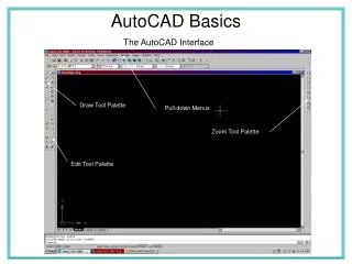
The AutoCAD Interface. AutoCAD Basics. Draw Tool Palette. Pull-down Menus. Zoom Tool Palette. Edit Tool Palette. AutoCAD Basics. The Drawing and Editing Interface.

AutoCAD Basics
E N D
Presentation Transcript
The AutoCAD Interface AutoCAD Basics Draw Tool Palette Pull-down Menus Zoom Tool Palette Edit Tool Palette
AutoCAD Basics The Drawing and Editing Interface A thorough understanding of absolute, relative and polar coordinates is suggested for utilizing AutoCAD’s drawing engine. Absolute = exact x,y position on the screen. Relative = going from a known position @x,y to the new position. Polar = moving from a known position @distance < theta (q). Use the command line to assist you in the “what to do next” process of drawing. It is located at the bottom of the screen and acts as the message line in Graphite. All of the creation tools are on the drawing tool palette. The “Line” tool allows you to draw continuous lines starting with the “first” point. Each subsequent point will generate a segment between them. The line is terminated by hitting “Enter”, the “Space bar” or “right mouse” clicking and selecting “Enter”. Circles are started with the default value for the “Radius”. Be sure to double the value or change the default to “Diameter” by typing “D” and “Enter” before clicking the circle’s center Line Circle Trim Erase The “Erase” tool show a pencil eraser icon and is used to delete the entire entity. Make sure that you select the icon, then select the object, and hit “Enter” to delete the entity or entities. The “Trim” works similar to Graphite. First select the tool, then select the boundary, hit “Enter” and select the part of the entity you wish to remove.
AutoCAD Basics The A-size Prototype Procedure 1.Open the “AutoCAD” program. 2. Select the “Line” tool. 3. Type the following coordinate positions: 0,0 + “Enter”,10,0 + “Enter”, 10,7.5 + “Enter”, 0,7.5 + “Enter”, C or 0,0 + “Enter”. This will draw our border 10 inches wide by 7.5 inches high. Type the letter ‘Z” + “E” + “Enter” 4. Select the “Offset” Tool ( looks like a race track on the “Modify” tool palette. 5. Click the bottom line with the little square pick box. Type the value of .38 + “Enter”. Select the side or direction you want to copy the new line. Click any where above the bottom line on the screen. 6. Select the “Offset” tool again and offset the horizontal spaces for the title block moving left to right with the spaces of 3.25, 3.25, reselect tool and offset 1, reselect and offset 1.25, reselect tool and offset .75. Figure 1
AutoCAD Basics The A-size Prototype Procedure 7. Select the ”Trim” tool. 8. Select the .38 offset line. 9. Hit “Enter” and click all the lines above the .38 inch offset line 10. Select the “Format” menu. 11. Select the “Text Style” option and set the “Font” to “Arial” and the “Height” to .125. Select “Apply” and “Close”. 12. Select the “Text” tool. Click the “Osnap” button at the bottom of the screen. 13. Make a text box across the first box in the title block. Look for the yellow box to mark the endpoint of the lines for the width and height. Select the “Font” to “Arial” and clink the “Properties” tab and select “Middle Center” and click the “Character” tab and type the generic name for your drawing title. 14. Complete the rest of the title block using the same procedure.
AutoCAD Basics The A-size Prototype Procedure 15. Select the ”Format” menu. 16. Select the “Layer” option. 17. Select the “New” button. 18. Create all of the following layers: Visible, Hidden, Center, Phantom, Construction, Dimension and Hatch. 19. Click on the color tab next to each layer and assign the appropriate colors for each layer. 20. Click on the line tab next to each layer and load the hidden2, center2 and the phantom2 linetypes.
AutoCAD Basics The A-size Prototype Procedure The completed layer settings will like the figure to the right..
AutoCAD Basics The A-size Prototype