AutoCAD
AutoCAD. Certification. Certification Test Description.

AutoCAD
E N D
Presentation Transcript
AutoCAD Certification
Certification Test Description • Our AutoCAD test measures your ability to design in two dimensions using AutoCAD. This test covers the following topics: Getting Started/ Organization, Creating Objects, Drawing, Editing, Layers, Color and Line types, Text, Dimensioning, Blocks, Attributes and Xrefs, Printing and Plotting, and Utilities.
Blocks, Attributes, & Xrefs Creating Objects Curved Objects, Hatching, and Lines Dimensioning Concepts, Creating, Dimensioning Styles, and Editing Drawing Calculating Areas, Distance, & Angles; Paper Space/ Model Space; Snaps, and Zoom & Pan Editing Chamfering/ Filleting, Copying Objects, Edit Commands, Editing Objects, Moving Objects, Resizing Objects, and Selecting Objects. Test Outline
Getting Started/ Organization AutoCAD Interface, Drawing Setup, and Modifying the AutoCAD Environment Layers, Colors, & Linetypes Printing and Plotting Text Line Text, Multiline Text, Text Editors, and Text Styles Utilities Importing/Exporting Files, Purging, and Scripts Test Outline Cont.
TestFormat • Online • 40 Multiple Choice Questions • 3 Minute time limit per question • Open book/ AutoCAD • No one else may assist you • Randomly Generated Questions
Scoring • Scores range from 0.00- 5.00 • 2.75 or better to pass (Standard Level) • 4.00 or better to pass (Master Level)
Trivia Info • The following slides contain helpful information that you will want/need to know to create a successful drawing in AutoCAD.
Command Codes • CO- Copy • C- Circle • L- Line • MI- Mirror • F- Fillet • E- Erase/Edit • CHA- Chamfer
Function Keys • F1 HELP • F2 FLIPSCREEN • F3 OSNAP • F4 TABLET • F5 ISOPLANE • F6 COORDINATE DISPLAY
Function Keys Cont. • F7 GRID • F8 ORTHO • F9 SNAP • F10 POLAR • F11 OTRACK
Special Function Keys • ESC- Cancels the current command, menu, or dialog box. • ENTER- Ends a command; or will repeat the previous command if the command line is blank • SPACE BAR- Same as the end key except when entering text.
Coordinate Display (F6) • In the ABSOLUTE mode: Displays the location of the crosshairs/ cursor in reference to the origin. The first number represents the horizontal (x axis) and the second number represents the vertical (y axis). • In RELATIVE POLAR mode: displays the distance and angle of the cursor from the last point entered.
SNAP (F9) • Increment Snap controls the movement of the cursor. If it is off the cursor will move smoothly. If it is ON, the cursor will jump in an incremental movement. The increment spacing can be changed, at any time using TOOLS/DRAFTING SETTINGS. The default spacing is .250
GRID (F7) • The grid is merely a visual “drawing aid”. The default spacing is 1 unit. You may change the grid spacing at any time using: TOOLS/DRAFTING SETTINGS.
ORTHO (F8) • When ORTHO is ON, the cursor movement is restricted to horizontal or vertical. When ORTHO is OFF, the cursor is free to move.
POLAR (F10) • POLAR TRACKING creates “alignment paths” at specified angles.
OSNAP (F3) • RUNNING OBJECT SNAP- specific object snaps can be set to stay active until you turn them off.
OTRACK (F11) • OBJECT SNAP TRACKING creates “alignment paths” at precise positions using object snap locations.
AutoCAD Key Terms
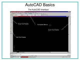
Drawing Area • The large area in the center of the screen. • This is where you draw. • The size can be changed at any time.
CrossHairs/ Cursor • The movement is controlled by the movement of the pointing device (mouse). • Use to locate points, make selections and draw objects.
Command Line • The three lines at the bottom of the screen. • This is where you enter commands and AutoCAD will prompt you to input information. • The number of lines visible can be changed.
Status Bar • Displays your content settings. • The settings can be turned on/off by clicking on the word (SNAP, GRID, ORTHO, etc) or by pressing the function keys associated with each.
LWT • Lineweight displays the width assigned to each object.
MODEL • Switches your drawing between paper space and model space.
BPOLY • Common types to bring up the boundary box. • Also used to make line segments for 1 uniform shape.
LIST • Used to get database info for an object. • Layer • Space • Center Point • Radius • Start Angle • End Angle • Length of line or arc
Multiple Drawing Environments: MDE • You can open as many files as you have memory for. • Like other Windows documents, you can work in any drawing by minimizing or maximizing the screen. • You can only copy, match properties and move in MDE.
Lineweights • Set by layers • LWT- turns them on or off
Filenames • Don’t use spaces if possible.
LISP • Programs allow you to combine math and AutoCAD functions and use products in your CAD drawings.
External Reference (XREF) • Used to share common objects. • Can bring an object from outside and put on screen, but not into drawing. • You can’t change on screen. Can only be changed at the network server origin.
XREF • Attach- attach to drawing • Detach- discard from drawing • Reload- made change from server, hit reload, and it picks up the current changes. • Bind- becomes a block and not an xref. (Becomes part of the drawing.)
When to bind an XREF • When you cant non-global changes. • When you send work to a client.
Linetype Codes • Linetypes start with the letter “A” • “A” stands for alignment field • A positive number represents the length of a dash • A negative number represents the length of a space • A dot will give you a space
Plotting • #1 (color), #1 (lwt) • #2 (color), #2 (lwt) • Plot style/ select form view/ color #1, lwt #1, color #2, lwt #2
Plot Units= Drawing Units • ¼=1 1=48 • 1/8=1 1=96 • ½=1 1=24
Stuff you should know/ understand • MView= creates viewport in paper space set aperture size= Tools/options/selection • Vmax= zoom max view you can get without regeneration • Nested Block= block within a block • If no justification is used, when you select text to edit, where does the grip show up?
Stuff you should know… cont. • In layer names do not use dots. • A view is a saved zoom in AutoCAD • Items that can be used in naming items • Numbers • Letters • Underscores • Hyphens