Download
1 / 125
1.26k likes | 1.43k Vues
Integrated Science Payload for the Solar Orbiter Mission Final Review. ESTEC– June 29 th 2004. Study overview. Study challenges and main steps. To reduce the mass budget by 25% in order to recover the payload mass assumption made for the system assessment study.

E N D
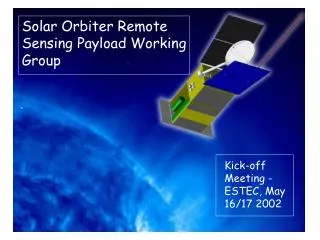
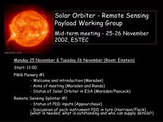
Integrated Science Payload for the Solar Orbiter Mission Final Review ESTEC– June 29th 2004 SolO ISP Study – FR - ESTEC – 29 June 2004 SOP-HO-ASF-023
Study overview SolO ISP Study – FR - ESTEC – 29 June 2004 SOP-HO-ASF-023
Study challenges and main steps • To reduce the mass budget by 25% in order to recover the payload mass assumption made for the system assessment study. • Mass reassessment of instruments as described in PDD shows opposite conclusion! • Clarification/homogeneisation/relaxation of resolution requirements • 1 arcsec spatial resolution / 150 km pixel targetted for all high resolution instruments • Allows to reduce instruments size from 1.5 m to 1 m length • Allows to come back within mass specification • Allows to better deal with solar flux • To deal with the SolO mission challenge of a complex suite of instruments for an ambitious journey toward the sun, at a cost in line with an ESA flexible mission. • First system level iterations indicates that S/C for shortest cruise missions were too heavy • Instrument size reduction • allows to design more compact spacecrat • Now mass compatible with shortest cruise mission, using SEP and direct Venus transfer • Remote sensing and in-situ Instrument I/F clarifications/consolidation • Allows to initiate system studies with consolidated data • Allows to promote I/F standardisation, to pave the way for an efficient development SolO ISP Study – FR - ESTEC – 29 June 2004 SOP-HO-ASF-023
Study team organisation Frederic FAYE Frederic FAYE Frederic FAYE Christian STELTER Omar EMAM SolO ISP Study – FR - ESTEC – 29 June 2004 SOP-HO-ASF-023
Study logic SolO ISP Study – FR - ESTEC – 29 June 2004 SOP-HO-ASF-023
Study schedule ISP for ISP for SolO SolO M1 M1 M2 M2 M3 M3 M4 M4 M5 M5 M6 M6 24/09/2003 24/09/2003 WM WM KO KO PM1 PM1 PM2 PM2 FP FP MTR MTR WPA WPA Management & Expertise Management & Expertise WP1 WP1 Instrument Performance & System Assessment Instrument Performance & System Assessment 110 110 Mission & Spacecraft assessment Mission & Spacecraft assessment 120 120 Instruments performance & system assessment Instruments performance & system assessment 130 130 Radiation & EMC assessment Radiation & EMC assessment WP2 WP2 Instrument Resource Reduction Instrument Resource Reduction 210 210 Resource reduction synthesis Resource reduction synthesis 220 220 Sensor architecture & technologies Sensor architecture & technologies 230 230 Mechanical Mechanical - - thermal architecture & technologies thermal architecture & technologies 240 240 Electrical Electrical - - functional architecture & technologies functional architecture & technologies 250 250 ISP support & ISP support & Bepi Bepi heritage heritage WP3 WP3 Conceptual design of Conceptual design of Rrsource Rrsource efficient payload efficient payload 310 310 ISP system engineering ISP system engineering 320 320 Sensor architecture & technologies Sensor architecture & technologies 330 330 Mechanical Mechanical - - thermal architecture & technologies thermal architecture & technologies 340 340 Electrical Electrical - - functional architecture & technologies functional architecture & technologies WP4 WP4 Payload technology planning & cost analysis Payload technology planning & cost analysis WP5 WP5 Shared payload subsystems planning & cost analysis Shared payload subsystems planning & cost analysis SolO ISP Study – FR - ESTEC – 29 June 2004 SOP-HO-ASF-023
Environment analyse Space enviromnent Contamination guidelines SolO ISP Study – FR - ESTEC – 29 June 2004 SOP-HO-ASF-023
Environment Analysis • Source Term: Mission Solar Proton Fluence SolO ISP Study – FR - ESTEC – 29 June 2004 SOP-HO-ASF-023
Environment Analysis • Total Dose (Cruise + Mission) SolO ISP Study – FR - ESTEC – 29 June 2004 SOP-HO-ASF-023
Environment Analysis • Source Term: Solar Wind • Solar wind carry considerable kinetic energy, typically ~1 keV for protons and ~4 keV for He++. This can result in sputtering from exposed surface materials • Flux ~ 1.3 E+9 particles/(cm² s) (average), Momentum flux ~ rv² very high >1E+16!! SolO ISP Study – FR - ESTEC – 29 June 2004 SOP-HO-ASF-023
Environment Analysis Radiation Effects and Consequences on SOLAR ORBITER P/L • Degradation of electronic components, detectors due to ionising dose • No significant problem for shielded (4mm) electronics and sensors (14 krad) • Non ionising absorbed dose (displacement) due to protons • Displacement in bipolar devices is an issue but generally negligible below about 3E+10 p/cm² (50 MeV) • Displacement on optical devices (optocoupler, APS, etc.) very critical => Solutions on parts level (hardening technology) and on system level (intelligent shielding is efficient), => APS remain problematic • Galactic Cosmic Ray induced effects (single event phenomena SEP) • no further problem for SOLO compared to missions at 1AU w/o geomag. Shielding • Solar event (proton and ion) induced upsets (single event phenomena SEP) • A factor of ~25 higher at 0.2 AU than in GEO • Measures in order to cover the problem: mainly on electronic design level (filtering, EDAC, TMR, etc.) • Interference with detector operation (background produced by secondary nuclear reactions) • Thorough analysis on proton interaction with materials (surface material, shielding structure) and evaluation of activation effects (spallation, neutron, gamma emission) • Radiation induced outgassing (radiolysis) and following contamination • Selection of non polymeric with non-halogenic content materials • Solar Wind Effects • Evaluation of solar wind degradation effects (sputtering) on surface materials (change of a/e, surface roughness, etc.) SolO ISP Study – FR - ESTEC – 29 June 2004 SOP-HO-ASF-023
Environment Analysis • Meteroid fluence on Solar Orbiter • Design parameters: v=45 km/s, r=2 g/cm³, impact angle 45° SolO ISP Study – FR - ESTEC – 29 June 2004 SOP-HO-ASF-023
Environment Analysis • Solar Dust exposure SolO ISP Study – FR - ESTEC – 29 June 2004 SOP-HO-ASF-023
Cleanliness Analysis EMC • EMC Control requires „normal“EMC measures on S/C level • EMC program/working group requested by RPW SolO ISP Study – FR - ESTEC – 29 June 2004 SOP-HO-ASF-023
Cleanliness Analysis Magnetic Cleanliness • MAG requires magnetic cleanliness plan (TBD), but according to Science Teams response (Sci-A/2004/069/AO, 9/6/2004) no anticipated problems stated. SolO ISP Study – FR - ESTEC – 29 June 2004 SOP-HO-ASF-023
Cleanliness Analysis Particulate/Organic Cleanliness • Cleanliness and Contamination Control follow ECSS-Q-70-01A Particulates: • Cleanroom conditions, e.g. CLASS 10 000 for PWA at all times Organic Cleanliness: • Materials not to be used: • polymeric materials with high outgassing potential • polymeric materials with low particle radiation stability (radiolysis) • Halogenated polymeric materials SolO ISP Study – FR - ESTEC – 29 June 2004 SOP-HO-ASF-023
Conclusions on environment and cleanliness • Environment assessement • Major care shall be taken against: • Displacement due to Proton (in particular with APS systems) • Solar events (protons and ions) induced upset • Solar wind effects (sputtering on thin layers) • Material selection (radiolysis) • No major concerns arise from total radiation dose and GCR • Contamination assessement • Cleanliness plan are needed for all payloads, covering • EMC cleanliness • Magnetic cleanliness • Particulate organic cleanliness (outgassing) • This will drive the allowable material list • At system level, an evaluation of Suitability of an Integrated Shielding System (Thermal, MM Dust, Radiation) deserves consideration SolO ISP Study – FR - ESTEC – 29 June 2004 SOP-HO-ASF-023
Remote sensing instruments VIM SolO ISP Study – FR - ESTEC – 29 June 2004 SOP-HO-ASF-023
Visible-light Imager and Magnetograph (VIM)Overview • Measurement of: • velocity fields using Doppler effect • magnetic fields using Zeeman effect • Magnetograph : imagery in narrow (5 pm FWHM ) spectral bands around a visible spectral line at different polarisation states line of sight (LOS) velocity magnetic field vector • Time resolution : 1 minute (5 x 4 polarisations) • Spatial resolution : • 0.5 arc-sec with 0.25 arc-sec sampling : 250 mm (PDD) • 1 arc-sec with 0.5 arc-sec sampling : 125 mm (new baseline) • Field : 2.7° (angular diameter of sun at 0.21 AU) • Split in 2 instruments : HRT for resolution and FDT for field • Stringent LOS stability: 0.02 arc-sec over 10 s (differential photometry) internal Image Stabilisation System SolO ISP Study – FR - ESTEC – 29 June 2004 SOP-HO-ASF-023
Visible-light Imager and Magnetograph (VIM)Functional block diagram HRT: High Resolution Telescope FO: Filtergraph Optics focus and image stabilisation mechanism visible filter PMP : Polarisation Module Package Fabry Perot in collimated beam selection mirror detector aperture door mechanism front end electronics 28 V collimator mechanism drive electronics camera back end electronics limb sensor FDT: Full Disk Telescope SolO ISP Study – FR - ESTEC – 29 June 2004 SOP-HO-ASF-023
VIM configuration, volume and mass resolution relaxation volume and mass reduction * excluding window, enclosure & radiators SolO ISP Study – FR - ESTEC – 29 June 2004 SOP-HO-ASF-023
Critical items and proposed alternatives • Critical technologies and alternatives • Polarisation Modulation Package : 10-3 polarisation accuracy, tuning1s • Liquid Crystal Variable Retarders: behaviour under radiations • alternative: wheel mechanism with polarisers • Fabry Perot: FWHM = 5 pm, FSR = 150 pm, 1s • LiNbO3 solid state etalons with spectral tuning achieved by high voltages:behaviour under radiations • alternatives: vacuum with piezo or thermal deformation, gaz with pressure control • proposed demonstrators in technological plan • Proposed VIM design modifications : • Narrow band entrance filter to minimize heat • Off-axis optical configuration for HRT( to avoid strong obturation by heat stop)or refractive system SolO ISP Study – FR - ESTEC – 29 June 2004 SOP-HO-ASF-023
Remote sensing instruments EUS SolO ISP Study – FR - ESTEC – 29 June 2004 SOP-HO-ASF-023
EUV Imager and Spectrometer (EUS)Overview • High resolution slit spectrometry of sun disk • Three spectral bands • 17 – 22 nm • 58 – 63 nm • 91.2 – tbd nm • Spatial resolution = sampling = 0.5 arc-sec (PDD) 1 arc-sec (new) • Diameter = 120 mm ( 60 mm) not driven by diffraction effects but by flux optics transmission is a key parameter (2 telescope options) • Spectral resolution = 1 pm/pixel (PDD) 2 pm/pixel (new) • Spectrometer concept: single element : toroidal varied line-space (TVLS) grating • Field of view = 34 arc-min driven by detector array size (4k 2k) • Spectral range = 4-5 nm driven by detector array size (4k 2k) • Internal raster mode • Internal LOS control system from VIM data (tbc) SolO ISP Study – FR - ESTEC – 29 June 2004 SOP-HO-ASF-023
EUV Imager and Spectrometer (EUS)Functional block diagram telescope single mirror or Wolter II relay optics with disperser proposed EUV filter slit as field stop detector front end electronics raster mode & LOS control by mirror tilting 28 V shutter mechanism drive electronics back end electronics SolO ISP Study – FR - ESTEC – 29 June 2004 SOP-HO-ASF-023
EUV Imager and Spectrometer (EUS)Recommandations • Normal Incidence System (NIS) for the telescope • EUS requires a large diameter entrance aperture (120 mm), leading to large solar heat loads, above 400 W at 0.21 AU Entrance EUV filter with radiative grid recommended • Al foil filter well adapted for two bands SolO ISP Study – FR - ESTEC – 29 June 2004 SOP-HO-ASF-023
High coupling with cold space Visible and UV are mainly reflected Alu radiator VDA for absorption limit 4.5 mm 240 mm sunshield 0.5 mm Alu foil 0.3 micron 0.3 mm substrat EUV is transmitted Satellite structure EUV Imager and Spectrometer (EUS)Radiative grid on Al foil • A radiative grille (black painted) parallel to Sun flux is conductively coupled to the metal filter, and allow to radiate the absorbed flux. The global emissivity of the filter assembly is highly increased. SolO ISP Study – FR - ESTEC – 29 June 2004 SOP-HO-ASF-023
EUS configuration, volume, mass resolution relaxation volume and mass reduction (1) : increase pixel to 8 µm would lead to a volume of about 960 x 240 x 180 (2) : ancillary equipment, thermal cover not yet accounted for SolO ISP Study – FR - ESTEC – 29 June 2004 SOP-HO-ASF-023
mirror radiator8 to 16 W to be rejected 700 mm 33.6 W on baffle 10% to 20% absorbed entrance diameter 67 mm 114 W pupil on mirror diameter 60 mm 80.4 W on mirror 80% to 90% reflected heat stop radiator59 to 67 Wto be rejected 5 W inside spectro 59 to 67 W absorbed by heat stop EUS with relaxed resolutionThermal issue • Proposed EUS design with relaxed resolution 60 mm pupil diameter re-opening of entrance filter trade-off • Option 1 : pupil on mirror SolO ISP Study – FR - ESTEC – 29 June 2004 SOP-HO-ASF-023
mirror radiator8 to 16 W to be rejected 700 mm 11.3 W on baffle 10% to 20% absorbed 80.4 W on mirror mirror diameter 67 mm 80% to 90% reflected pupil at entrance diameter 60 mm 5 W inside spectro 59 to 67 W absorbed by heat stop EUS with relaxed resolutionThermal issue • Option 2 : pupil at instrument entrance • Advantage: reduced heat load on baffle • Drawback: oversized primary mirror, optical design to be reassessed entrance diameter 60 mm 91.7 W heat stop radiator59 to 67 Wto be rejected SolO ISP Study – FR - ESTEC – 29 June 2004 SOP-HO-ASF-023
EUV Imager and Spectrometer (EUS)Critical points and open issues • Option with entrance filter • obturation of filter radiator : impact on throughput • EUV filter thermal issue is solved • breadboard in technological plan • Option without entrance filter (with reduced pupil) • thermal control critical: heat rejection of heat stop; thermo-elastic deformationstypical tolerance 10µm / 100µrad 5°C on SiC structure, some tenths of °C on mirror gradients • primary mirror multilayer coating behaviour with high thermal flux to be assessed • EUV Detectors • 2 k x 2 k format back-thinned CMOS with 5 µm (tbc) pixels • breadboard in technological plan • Toroidal varied-line gratings: studies in US and Italy; maturity of technology ? • Coatings from 17 to 100 nm: multilayer, gold, SiC ; 2 or 3 bands ? SolO ISP Study – FR - ESTEC – 29 June 2004 SOP-HO-ASF-023
Remote sensing instruments EUI SolO ISP Study – FR - ESTEC – 29 June 2004 SOP-HO-ASF-023
EUV Imager (EUI)Overview • Imaging of the sun disk in EUV • Resolution/sampling = 0.5 arc-sec (PDD) 1 arc-sec (new) • Field of view = 2.7° (sun angular diameter at 0.21 AU) • Field/resolution = 20 000 (10 000) split in 2 instruments • HRI for resolution: 0.5 arc-sec ( 1 arc-sec) in 34 arc-min field (4k x 4k 2k x 2k detector array) • FSI for field: 4.75 arc-sec ( 9.5 arc-sec) in 5.4° field (4k x 4k 2k x 2k detector array); field of FSI is twice the sun angular diameter to account for HRI depointing • HRI spectral bands: 13.3 nm, 17.4 nm, 30.4 nm 3 different HRI telescopes optimised for each spectral band • FSI spectral bands: tbd in 17.1 – 30.4 nm single telescope • Diameter of HRIs and FSI = 20 mm driven by radiometry and not diffraction could be reduced to 10 mm with relaxed resolution • Internal LOS control system from VIM data (tbc) SolO ISP Study – FR - ESTEC – 29 June 2004 SOP-HO-ASF-023
EUV Imager (EUI)Functional block diagram EUV filter telescope relay optics baffle field stop detector front end electronics aperture door mechanism LOS control by mirror tilting 28 V back end electronics mechanism drive electronics SolO ISP Study – FR - ESTEC – 29 June 2004 SOP-HO-ASF-023
9 W absorbed by baffle after reflection on foil filter 7 W absorbed directly by baffle 2.7 W absorbed after reflection on foil 10 W reach the foil filter spread on 66 mm 1 W absorbed by foil 9 W reflected back towards baffle 3 W reach foil filter 0.3 W absorbed by foil 2.7 W reflected back towards baffle 10 W 10 W 2.7° field 0.3° field 1190 mm 1500 mm entrance pupil diameter = 20 mm foil filter diameter = 35 mm entrance pupil diameter = 20 mm foil filter diameter = 133 mm EUV Imager (EUI)Bafflage and EUV filter HRI FSI SolO ISP Study – FR - ESTEC – 29 June 2004 SOP-HO-ASF-023
HRI : single structure ("optical bench") for all 3 telescopes baffles thermally decoupled from the "optical bench" to minimise heat-flux and thermoelastic distortion FSI : baffle decoupled from optical bench filter supported by baffle EUV Imager (EUI)HRI and FSI configurations SolO ISP Study – FR - ESTEC – 29 June 2004 SOP-HO-ASF-023
EUV Imager (EUI)Evolution of design resolution relaxation volume and mass reduction * excluding window, enclosure & radiators& other ancillary equipment SolO ISP Study – FR - ESTEC – 29 June 2004 SOP-HO-ASF-023
EUV Imager (EUI)Critical points and open issues • Heat rejection of EUV filters and baffles • EUV Detectors ( as EUS) • back-thinned CMOS • 4 k x 4 k 2 k x 2 k format with 9 µm pixels • alternative detectors : Diamond or GaN/AlGaN credible in large format ? • Cooling of CMOS detectors at – 80°C • Telemetry: huge compression or data selection required SolO ISP Study – FR - ESTEC – 29 June 2004 SOP-HO-ASF-023
Remote sensing instruments COR SolO ISP Study – FR - ESTEC – 29 June 2004 SOP-HO-ASF-023
Coronograph (COR)Overview • Observation of sun corona between 1.2 and 3.5 radii • Coronograph • needs of occulters to mask the sun disk • optical design with field stop and Lyot stop • Spectral bands • 450 – 600 nm • 121.6 10 nm • 30.4 5 nm (optional) • Field of view = 9.2° (corona angular diameter at 0.21 AU) • Spatial resolution = spatial sampling = 8 arc-sec driven by 4 k x 4 k detector array 16 arc-sec with 2 k x 2 k SolO ISP Study – FR - ESTEC – 29 June 2004 SOP-HO-ASF-023
Coronograph (COR)Functional block diagram EUV/VIS dichroic image internal occulter achromatic polarimeter UV filter wheel mechanism external occulter relay optics entrance pupil EUV detector front end electronics telescope pupil Lyot stop sun disk rejection mirror aperture door mechanism VIS detector COR pointing mechanism back end electronics 28 V mechanism drive electronics SolO ISP Study – FR - ESTEC – 29 June 2004 SOP-HO-ASF-023
Coronograph (COR)Overall configuration COR volume not in line with other remote sensing instruments recommandation : decrease distance external occulter to pupil with related decrease of pupil diameter (at constant vignetting) * To be assessed on science grounds SolO ISP Study – FR - ESTEC – 29 June 2004 SOP-HO-ASF-023
Coronograph (COR) Critical points and open issues • Recommandations: • Mass and volume not in line with other remote sensing instrumentsrecommandation : reduction of sampling distance shrinkage of instrument by factor 2 • removal of pointing mechanism COR off during offset pointing) duty cycle • whole design to be worked out further • Critical points and open issues • Heat rejection of external occulter • Design of sun disk rejection mirror • EUV coating of mirrors compatible with visible light • Feasibility of the EUV/VIS dichroic (visible light reflected, EUV get through) • EUV detectors : see EUS & EUI SolO ISP Study – FR - ESTEC – 29 June 2004 SOP-HO-ASF-023
Remote sensing instruments STIX SolO ISP Study – FR - ESTEC – 29 June 2004 SOP-HO-ASF-023
Spectrometer Telescope for Imaging X-rays (STIX) Overview • Imagery of sun disk in X-rays • Spectral bands: hard X-rays = 4 – 150 keV ; 8 - 310 pm • Use of X-rays techniques: • pseudo imaging by grids • X-ray position/energy detectors : CdZnTe • Spatial resolution = sampling = 2.5 arc-sec • Field of view • FWHM imaging field of view = 24 arc-min • Spatially integrated spectroscopy field of view = 3° • Energy resolution = 2 to 4 keV in 16 energy levels SolO ISP Study – FR - ESTEC – 29 June 2004 SOP-HO-ASF-023
Spectrometer Telescope for Imaging X-rays (STIX) Functional block diagram filter Fresnel lens aspect system VIS detector X-ray detector front end electronics rear grid aspect system front grid 28 V back end electronics SolO ISP Study – FR - ESTEC – 29 June 2004 SOP-HO-ASF-023
Spectrometer Telescope for Imaging X-rays (STIX) Critical points and open issues • Good level of maturity in general • Becomes the longest remote sensing instrument following reduction exercise on all other instruments • Length reduction down to 1 m should be investigated, in line with dimensions of all other remote sensing instruments. • This may require to reduce the grid pitch if resolution needs to be kept • Will avoid to constrain the S/C design snowball impact on structure mass at S/C structure level, on orbiter and on propulsion module • Aspect system design to be investigated further • Detector CdZnTe : space qualified prototype but design to be adapted to STIX SolO ISP Study – FR - ESTEC – 29 June 2004 SOP-HO-ASF-023
Synthesis for remote sensing instruments SolO ISP Study – FR - ESTEC – 29 June 2004 SOP-HO-ASF-023
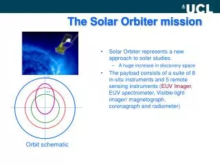
flux collector inst 2 inst 1 inst 4 inst 3 Why integration of payloads is not practical for Solar Orbiter ? Common telescope with shared focal plane : ex Hubble, JWST, Herschell astronomy of faint objects + very high resolution large pupil reduced spectral range ; Hubble = visible, JWST = IR, Hershell = submillimeter small instruments with respect to collector Solar orbiter : reduced collector diameter (sun at 0.2 AU) large instrument dimensions ; from visible to X-rays very specific instruments: coronograph no possibility and no interest to share optics conclusion : no suite only individal instruments SolO ISP Study – FR - ESTEC – 29 June 2004 SOP-HO-ASF-023
Remote sensing instruments geometrical IRD • From the mechanical configuration, IRD are updated • Overall volume including bipodes • Electronic not included. Sizing based on DE boards • Volume for connectors, closure box not included SolO ISP Study – FR - ESTEC – 29 June 2004 SOP-HO-ASF-023