Download

1 / 36
360 likes | 494 Vues
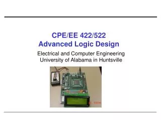
CPE/EE 422/522 Advanced Logic Design L03. Electrical and Computer Engineering University of Alabama in Huntsville. Outline. What we know Combinational Networks Analysis, Synthesis, Simplification, Building Blocks, PALs, PLAs, ROMs Sequential Networks: Basic Building Blocks

E N D
CPE/EE 422/522Advanced Logic DesignL03 Electrical and Computer EngineeringUniversity of Alabama in Huntsville
Outline • What we know • Combinational Networks • Analysis, Synthesis, Simplification,Building Blocks, PALs, PLAs, ROMs • Sequential Networks: Basic Building Blocks • What we do not know • Design: Mealy, Moore • Sequential Network Timing • Setup and hold times • Max clock frequency UAH-CPE/EE 422/522 AM
Sequential Networks • Have memory (state) • Present state depends not only on the current input, but also on all previous inputs (history) • Future state depends on the current input and state X = x1 x2... xn Q = Q1 Q2... Qk Z = z1 z2... zm x1 z1 x2 z2 Q Flip-flops are commonly used as storage devices:D-FF, JK-FF, T-FF xn zm UAH-CPE/EE 422/522 AM
Review: Clocked D Flip-Flop with Rising-edge Trigger Next state The next state in response to the rising edge of the clock is equal to the D input before the rising edge UAH-CPE/EE 422/522 AM
Review: Clocked JK Flip-Flop Next state JK = 00 => no state change occurs JK = 10 => the flip-flop is set to 1, independent of the current state JK = 01 => the flip-flop is always reset to 0 JK = 11 => the flip-flop changes the state Q+ = Q’ UAH-CPE/EE 422/522 AM
Review: Clocked T Flip-Flop Next state T = 1 => the flip-flop changes the state Q+ = Q’ T = 0 => no state change UAH-CPE/EE 422/522 AM
Review: S-R Latch, Transparent D-Latch UAH-CPE/EE 422/522 AM
Mealy Sequential Networks General model of Mealy Sequential Network (1) X inputs are changed to a new value • After a delay, the Z outputs and next state appear at the output of CM (3) The next state is clocked into the state register and the state changes UAH-CPE/EE 422/522 AM
x z Q An Example: 8421 BCD to Excess3 BCD Code Converter UAH-CPE/EE 422/522 AM
State Graph and Table for Code Converter UAH-CPE/EE 422/522 AM
State Assignment Rules UAH-CPE/EE 422/522 AM
Transition Table UAH-CPE/EE 422/522 AM
K-maps UAH-CPE/EE 422/522 AM
Realization UAH-CPE/EE 422/522 AM
Sequential Network Timing • Code converter • X = 0010_1001 => Z = 1110_0011 Changes in X are not synchronized with active clock edge => glitches (false output), e.g. at tb UAH-CPE/EE 422/522 AM
Sequential Network Timing (cont’d) Timing diagram assuming a propagation delay of 10 ns for each flip-flop and gate (State has been replaced with the state of three flip-flops) UAH-CPE/EE 422/522 AM
Setup and Hold Times • For a real D-FF • D input must be stable for a certain amount of time before the active edge of clock cycle => Setup time • D input must be stable for a certain amount of timeafter the active edge of the clock => Hold time • Propagation time: from the time the clock changes to the time the output changes Manufacturers provide minimum tsu, th, and maximum tplh, tphl UAH-CPE/EE 422/522 AM
Maximum Clock Frequency - Max propagation delay through the combinational network - Max propagation delay from the time the clock changes to the flip-flop output changes { = max(tplh, tphl)} - Clock period Example: UAH-CPE/EE 422/522 AM
Hold Time Violation • Occur if the change in Q fed back through the combinational network and cause D to change too soon after the clock edge Hold time is satisfied if: What about X? Make sure that input changes propagate to the flip-flops inputs such that setup time is satisfied. Make sure that X does not change too soon after the clock. If X changes at time ty after the active edge, hold time is satisfied if UAH-CPE/EE 422/522 AM
Moore Sequential Networks Outputs depend only on present state! X = x1 x2... xn Q = Q1 Q2... Qk Z = z1 z2... zm x1 z1 x2 z2 Q xn zm UAH-CPE/EE 422/522 AM
General Model of Moore Sequential Machine Outputs depend only on present state! Combinational Network Outputs(Z) Next State Inputs(X) State(Q) State Register Combinational Network Clock X = x1 x2... xn Q = Q1 Q2... Qk Z = z1 z2... zm UAH-CPE/EE 422/522 AM
S10 S9 S0 S6 S1 S2 S7 S3 S8 S5 S4 1 0 1 1 1 0 0 0 0 0 1 Code Converter: Moore Machine Start 1 0 NC C 1 0 0 1 NC C C 0 1 0 0 1 1 NC NC C 1 0 0 1 0 0 1 NC 1 NC 0 UAH-CPE/EE 422/522 AM
Start S8 S2 S5 S10 S9 S3 S6 S1 S0 S7 S4 1 0 1 1 0 0 0 1 0 1 1 0 0 NC C 1 0 0 1 NC C C 0 1 0 0 1 1 NC NC C 1 0 0 1 0 0 1 NC 1 NC 0 Code Converter: Moore Machine Do we need state S0? How many states does Moore machine have?How many states does Mealy machine have? UAH-CPE/EE 422/522 AM
Start S8 S2 S5 S10 S9 S3 S6 S1 S0 S7 S4 1 0 1 1 0 0 0 1 0 1 1 0 0 NC C 1 0 0 1 NC C C 0 1 0 0 1 1 NC NC C 1 0 0 1 0 0 1 NC 1 NC 0 Moore Machine: State Table Note: state S0 could be eliminated (S0 == S9), if S9 was start state! UAH-CPE/EE 422/522 AM
Moore Machine Timing • X = 0010_1001 => Z = 1110_0011 Moore Mealy UAH-CPE/EE 422/522 AM
S0 S2 S6 S7 S3 S1 S5 S4 State Assignments Guidelines to reduce the amount of combinational logic Rule I: (S0, S9, S10), (S4, S5), (S6, S7) Rule II: (S1, S2), (S3, S4), (S4, S5), (S6, S7), (S7, S8), (S9, S10) Rule III: (S0, S2, S4, S6, S8, S9)(S1, S3, S5, S7, S10) Q1Q2 01 10 00 11 Q3Q4 s10 S8 S9 00 S0 – 0010 S1 - 0111 …. S10 - 0100 01 11 10 UAH-CPE/EE 422/522 AM
Moore Machine: Another Example A Converter for Serial Data Transmission: NRZ-to-Manchester • Coding schemes for serial data transmission • NRZ: nonreturn-to-zero • NRZI: nonreturn-to-zero-inverted • 0 in input sequence – the bit transmitted is the same as the previous bit; • 1 in input sequence – transmit the complement of the previous bit • RZ: return-to-zero • 0 – 0 for full bit time; 1 – 1 for the first half, 0 for the second half • Manchester UAH-CPE/EE 422/522 AM
Moore Network for NRZ-to-Manchester UAH-CPE/EE 422/522 AM
Moore Network for NRZ-to-Manchester UAH-CPE/EE 422/522 AM
Synchronous Design • Use a clock to synchronize the operation of all flip-flops, registers, and counters in the system • all changes occur immediately following the active clock edge • clock period must be long enough so that all changes flip-flops, registers, counters will have time to stabilize before the next active clock edge • Typical design: Control section + Data Section Data registersArithmetic Units Counters Buses, Muxes, … Sequential machineto generate control signals to control the operation of data section UAH-CPE/EE 422/522 AM
Data section // s= n*(n+a) // R1=n, R2=a // R1=s Design flowchart for SMUL operation Design Control section S0 S1 F 0 0 B 0 1 B – C0 1 0 B + C0 1 1 A + B An Example UAH-CPE/EE 422/522 AM
Timing Chart for System with Falling-edge Devices UAH-CPE/EE 422/522 AM
Timing Chart for System with Rising-edge Devices UAH-CPE/EE 422/522 AM
Principles of Synchronous Design • Method • All clock inputs to flip-flops, registers, counters, etc.,are driven directly from the system clock or from the clock ANDed with a control signal • Result • All state changes occur immediately following the active edge of the clock signal • Advantage • All switching transients, switching noise, etc., occur between the clock pulses and have no effect on system performance UAH-CPE/EE 422/522 AM
Asynchronous Design • Disadvantage - More difficult • Problems • Race conditions: final state depends on the order in which variables change • Hazards • Special design techniques are needed to cope with races and hazards • Advantages = Disadvantages of Synchronous Design • In high-speed synchronous design propagation delay in wiring is significant => clock signal must be carefully routed so that it reaches all devices at essentially same time • Inputs are not synchronous with the clock – need for synchronizers • Clock cycle is determined by the worst-case delay UAH-CPE/EE 422/522 AM
To Do • Read • Textbook chapters 1.6, 1.7, 1.8, 1.10, 1.11, 1.12 UAH-CPE/EE 422/522 AM