Understanding LC-3 Computer Architecture and Machine Instructions
200 likes | 335 Vues
This guide explores the LC-3 computer architecture, covering memory mapping, machine instructions, and address modes. Key concepts include the instruction cycle (fetch, decode, evaluate, execute, and store), the Program Status Word, and important registers in the CPU such as the PC, IR, and MAR. It also details the different types of machine instructions including data movement and operate instructions, as well as how to program in machine code to perform operations like addition and subtraction of integers. Ideal for learners in computer architecture.

Understanding LC-3 Computer Architecture and Machine Instructions
E N D
Presentation Transcript
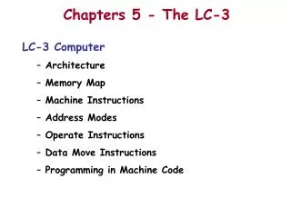
Chapters 5 - The LC-3 LC-3 Computer Architecture Memory Map Machine Instructions Address Modes Operate Instructions Data Move Instructions Programming in Machine Code
The LC-3 Computeravon Neumannmachine The Instruction Cycle: • Fetch: Next Instruction from Memory • (PC) (points to) next instruction • PC (PC) + 1 • Decode: Fetched Instruction • Evaluate: Instr &Address (es) • (find where the data is) • Fetch: Operand (s) • (get data as specified) • Execute: Operation • Store: Result • (if specified) PSW Memory PSW (Program Status Word): Bits: 15 10 9 8 2 1 0 | S| |Priority| | N| Z| P|
Important Registers in the CPU • 8 General Purpose Registers – Holds Data or Addresses • PC – Points to the next instruction to be executed • IR – holds the instruction being executed • MAR – Holds the address of the memory location being accessed • MDR – Hold the data to be written into memory or the date read from memory • PSW (includes NZP) – holds the status of the program being executed (NZP: Negative, Zero, Positive result of an operate instruction)
LC-3 Memory Map (64K of 16 bit words) 256 words (We will get to theses later) 256 words (We will get to these later) 23.5 K words ? 39.5 K words ? 512 words
Computer Machine Instruction Formats • What is IN an instruction? • Operation code– what to do • Input Operand(s)– where to get input operands (memory, registers) • Output Operand(s)– Where to put results (memory, registers) • What are the major instruction types? • Data Movement (load, store, etc.) • Operate (add, sub, mult, OR, AND, etc.) • Control (branch, jump to subroutine, etc.)
LC-3 Instructions (Fig 5.3 & Appendix a) • Addressing Modes • Register • (Operand is in one of the 8 registers) • PC-relative • (Operand is “offset” from where the PC points • - offsets are sign extended to 16 bits) • Base + Offset (Base relative) • (Operand is “offset” from the contents of a register) • Immediate • (Operand is in the instruction) • Indirect • (The “Operand” points to the real address of Operand • – rather than being the operand) • Note: The LC-3 has No Direct Addressing Mode
Operate Instructions • There are only three operate Instructions: ADD, AND, NOT • The Source and Destination operands are: Registers
NOT (Register) Note: Src and Dstcould be the same register.
ADD/AND (Immediate) Note: Immediate field issign-extended to 16 bits.
Data Movement Instructions • Load -read data from memory to a register • LD: PC-relative mode [0010 DR PCoffset9] • LDI: indirect mode [1010 DR PCoffset9] • LDR: base+offset mode [0110 DR BaseR offset6] • Store - write data from a register to memory • ST: PC-relative mode [0011 DR PCoffset9] • STI: indirect mode [1011 DR PCoffset9] • STR: base+offset mode [0111 DR BaseR offset6] • Load effective address – address saved in register • LEA: PC-relative mode [1110 DR PCoffset9]
Programming in Machine Code Write a program in machine code which: • Adds two integers • The program will be stored in the computer beginning in location x3000 • The integers, 26 and 67, will be stored in locations x3010 & x3011 • The result will be stored in location x3012
Programming in Machine Code Modify the program to: • Subtract two integers • The program will be stored in the computer beginning in location x3000 • The integers, 26 and 67, will be stored in locations x3010 & x3011 • The result will be stored in location x3012