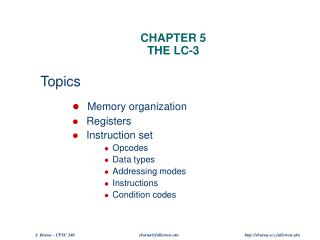
Chapter 5 The LC-3
Chapter 5 The LC-3. Data Movement Instructions. Load -- read data from memory to register LD: PC-relative mode LDR: base+offset mode LDI: indirect mode Store -- write data from register to memory ST: PC-relative mode STR: base+offset mode STI: indirect mode

Chapter 5 The LC-3
E N D
Presentation Transcript
Data Movement Instructions • Load -- read data from memory to register • LD: PC-relative mode • LDR: base+offset mode • LDI: indirect mode • Store -- write data from register to memory • ST: PC-relative mode • STR: base+offset mode • STI: indirect mode • Load effective address -- compute address, save in register • LEA: immediate mode • does not access memory
PC-Relative Addressing Mode • Want to specify address directly in the instruction • But an address is 16 bits, and so is an instruction! • After subtracting 4 bits for opcodeand 3 bits for register, we have 9 bits available for address. • Solution: • Use the 9 bits as a signed offset from the current PC. • 9 bits: • Can form any address X, such that: • Remember that PC is incremented as part of the FETCH phase; • This is done before the EVALUATE ADDRESS stage.
LD (PC-Relative) RDst<- M[ PC + IR[8:0] ] Note: The ALU is shown performing the add, but there may be a separate adder for address generation.
Base + Offset Addressing Mode • With PC-relative mode, can only address data within 256 words of the instruction. • What about the rest of memory? • Solution #1: • Use the value in a register to generate a full 16-bit address. • 4 bits for opcode, 3 for src/dest register,3 bits for base register -- remaining 6 bits are usedas a signed offset. • Offset is sign-extended before adding to base register.
Indirect Addressing Mode • With PC-relative mode, can only address data within 256 words of the instruction. • What about the rest of memory? • Solution #3: • Read address from memory location,then load/store to that address. • First address is generated from PC and IR(just like PC-relative addressing), thencontent of that address is used as target for load/store.
Load Effective Address • Computes address like PC-relative (PC plus signed offset) and stores the result into a register. • Note: The address is stored in the register, not the contents of the memory location.
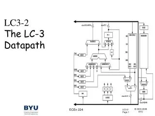
LC-3 Data PathRevisited Filled arrow = info to be processed. Unfilled arrow = control signal.
Using Branch and Load Instructions • Compute sum of 12 integers.Numbers start at location x3100. Program starts at location x3000. R1 x3100R3 0R2 12 R2=0? R4 M[R1]R3 R3+R4R1 R1+1 R2 R2-1 NO YES