LCD Interfacing with 8051
LCD Interfacing with 8051. LCD operation in contrast to LED the ability to display numbers, characters and graphics incorporation of a refreshing controller into the LCD. Ease of programming for characters and graphics. Liquid Crystal Displays (LCDs) cheap and easy way to display text

LCD Interfacing with 8051
E N D
Presentation Transcript
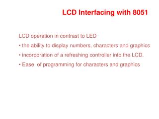
LCD Interfacing with 8051 LCD operation in contrast to LED • the ability to display numbers, characters and graphics • incorporation of a refreshing controller into the LCD. • Ease of programming for characters and graphics
Liquid Crystal Displays (LCDs) • cheap and easy way to display text • Various configurations (1 line by 20 X char upto 8 lines X 80 ). • Integrated controller • The display has two register • command register • data register • By RS you can select register • Data lines (DB7-DB0) used to transfer data and commands
Microcontroller E communications bus R/W RS DB7–DB0 8 LCD controller LCD Module Alphanumeric LCD Interfacing • Pinout • 8 data pins D7:D0 • RS: Data or Command Register Select • R/W: Read or Write • E: Enable (Latch data) • RS – Register Select • RS = 0 Command Register • RS = 1 Data Register • R/W = 0 Write , R/W = 1 Read • E – Enable • Used to latch the data present on the data pins. • D0 – D7 • Bi-directional data/command pins. • Alphanumeric characters are sent in ASCII format.
LCD Commands • The LCD’s internal controller can accept several commands and modify the display accordingly. These commands would be things like: • Clear screen • Return home • Decrement/Increment cursor • After writing to the LCD, it takes some time for it to complete its internal operations. During this time, it will not accept any new commands or data. • We need to insert time delay between any two commands or data sent to LCD
Sending commands and data to LCD with a time delay. Example : Write an ALP to initialize the LCD and display message “NO”. Say the command to be given is :38H (2 lines ,5x7 matrix), 0EH (LCD on, cursor on), 01H (clear LCD), 06H (shift cursor right), 86H (cursor: line 1, pos. 6) • P1.0-P1.7 are connected to lcd data pins D0-D7. • P2.0 is connected to RS pin of lcd. • P2.1 is connected to R/W pin of lcd. • P2.2 is connected to E pin of lcd.
ORG 00H MOV A,#38H ACALL COMNWRT ACALL DELAY MOV A,#0EH ; display on, cursor blinking ACALL COMNWRT ACALL DELAY MOV A,#01H ;clear display screen ACALL COMNWRT ACALL DELAY MOV A,#06H ;increment cursor, (shift to right) ACALL COMNWRT ACALL DELAY MOV A,#86H ACALL COMNWRT ACALL DELAY
MOV A,#’N’ ACALL DATAWRT ACALL DELAY MOV A,#’O’ ACALL DATAWRT AGAIN: SJMP AGAIN COMNWRT: MOV P1,A CLR P2.0 CLR P2.1 SETB P2.2 ACALL DELAY CLR P2.2 RET
DATAWRT: MOV P1,A SETB P2.0 CLR P2.1 SETB P2.2 ACALL DELAY CLR P2.2 RET DELAY: MOV R3,#50H HERE2: MOV R4,#255H HERE: DJNZ R4,HERE DJNZ R3,HERE2 RET END
Programming LCD in C(Busy flag is D7 and can be read and if D7=1 when R/W=1 and RS=0 then LCD is busy taking care of internal operations and will not accept any information. If D7=0, then it will accept information) • Write an 8051 C program to send letters ‘A’, ‘R’, and ‘M’ to the LCD using the busy flag method. • #include <reg51.h> • sfr ldata = 0x90; //P1=LCD data pins • sbit rs = P2^0; • sbit rw = P2^1; • sbit en = P2^2; • sbit busy = P1^7;
void main() • { • lcdcmd(0x38); • lcdcmd(0x0E); • lcdcmd(0x01); • lcdcmd(0x06); • lcdcmd(0x86); //line 1, position 6 • lcddata(‘A’); • lcddata(‘R’); • lcddata(‘M’); • }
void lcdcmd(unsigned char value) • { • lcdready(); //check the LCD busy flag • ldata = value; //put the value on the pins • rs = 0; • rw = 0; • en = 1; //strobe enable pin • MSDelay(1); • en = 0; • return; • }
void lcddata(unsigned char value){ • lcdready(); //check the LCD busy flag • ldata = value; //put the value on the pins • rs = 1; • rw = 0; • en = 1; //strobe the enable pin • MSDelay(1); • en = 0; • return;
void lcdready() • { • busy = 1; //make the busy pin at input • rs = 0; • rw = 1; • while(busy==1) • { //wait here for busy flag • en = 0; //strobe the enable pin • MSDelay(1); • en = 1; • } • }
void Msdelay(unsigned int itime) • { • unsigned int i, j; • for(i=0;i<itime;i++) • for(j=0;j<1275;j++); • }
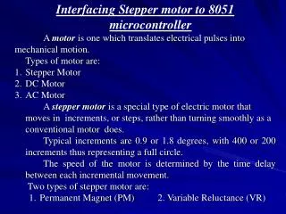
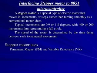
Stepper Motor Interfacing • Stepper motor is a widely used device that translates electrical pulses into mechanical movement. • Stepper motor is used in applications such as; disk drives, dot matrix printer, robotics etc. • Stepper motors commonly have a permanent magnet rotor (also called the shaft) surrounded by a stator
Commonly used stepper motors have four stator windings that are paired with a center – tapped common. Such motors are called as four-phase or unipolar stepper motor. • It has a permanent magnet rotor which is surrounded by a stator. • a practical PM stepper motor will have 1.8 degrees step angle and 50 tooth on its rotor. • There are 8 main poles on the stator, each having 5 tooth in the pole face
Stepper Motor Selection • Permanent Magnet / Variable Reluctance • Unipolar vs. Bipolar • Number of Stacks • Number of Phases • Degrees Per Step • Microstepping • Pull-In/Pull-Out Torque • Detent Torque
Most common stepper motors have 4 stator windings that are paired with a center-tapped common as shown in the fig. • This type of stepper motor is commonly referred to as a four phase or unipolar stepper motor • The center tap allows a change of current direction in each of two coils when a winding is grounded, there by resulting in a polarity change of the stator
The stator is a magnet over which the electric coil is wound. • One end of the coil is connected commonly either to ground or +5V. The other end is provided with a fixed sequence such that the motor rotates in a particular direction. • Stepper motor shaft moves in a fixed repeatable increment, which allows one to move it to a precise position. Direction of the rotation is dictated by the stator poles. Stator poles are determined by the current sent through the wire coils.
Step Angle • Step angle is defined as the minimum degree of rotation with a single step. • No of steps per revolution = 360° / step angle • Steps per second = (rpm x steps per revolution) / 60 • Example: step angle = 2° • No of steps per revolution = 180
One Phase on(Wave drive four step sequence) (Normal four step sequence)
Program: Write an ALP to rotate the stepper motor clockwise / anticlockwise continuously with full step sequence. • MOV A,#66H • BACK: MOV P1,A • RR A • ACALL DELAY • SJMP BACK • DELAY: MOV R1,#100 • UP1: MOV R2,#50 • UP: DJNZ R2,UP • DJNZ R1,UP1 • RET • Note: motor to rotate in anticlockwise use instruction RL A instead of RR A
: A switch is connected to pin P2.7. Write an ALP to monitor the status of the SW. If SW = 0, motor moves clockwise and if SW = 1, motor moves anticlockwise. • ORG 0000H • SETB P2.7 • MOV A, #66H • MOV P1,A • TURN: JNB P2.7, CW • RL A • ACALL DELAY • MOV P1,A • SJMP TURN • CW: RR A • ACALL DELAY • MOV P1,A • SJMP TURN
Write an ALP to rotate a motor 90° clockwise. Step angle of motor is 2°. • Step angle = 2° • Steps per revolution = 180 • For 90° rotation the no of steps is 45 • ORG 0000H • MOV A, #66H • MOV R0, #45 • BACK: RR A • MOV P1, A • ACALL DELAY • DJNZ R0, BACK • END
Programming stepper motor in ‘c’ • #include <reg51.h> • void main () • { • while (1) • { • P1=0x66; • MSDELAY (200); • P1=0x33; • MSDELAY (200); • P1=0x99; • MSDELAY (200); • P1=0xCC; • MSDELAY (200); • } • } • void MSDELAY (unsigned char value) • { • unsigned intx,y; • for(x=0;x<1275;x++) • for(y=0;y<value;y++); • }
#include <REG51xD2.H> void delay(unsigned int x) /* Delay Routine */ { for(;x>0;x--);} main(){ unsigned char Val,i; while(1) { Val = 0x88; for(i=0;i<4;i++) { P0 = Val; Val = Val>>1; delay(575); }}}
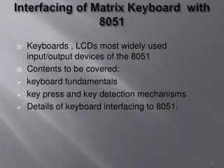
Keyboard interface • Organized in a matrix of rows and columns • The CPU accesses both rows and columns through ports • When a key is pressed, a row and a column make a contact; otherwise there is no connection between rows and columns • Fig shows a 4x4 matrix connected to 2 ports • Rows are connected to an output port and the columns are connected to an input port
Scanning and Identifying the Key: A 4X4 matrix keyboard
It is the function of the microcontroller to scan the keyboard continuously to detect and identify the key pressed • To detect a pressed key, the microcontroller grounds all rows by providing 0 to the output latch, then it reads the columns • If the data read from columns is D3 – D0 =1111, no key has been pressed and the process continues till key press is detected
If one of the column bits has a zero, this means that a key press has occurred For example, if D3 – D0 = 1101, this means that a key in the D1 column has been pressed After detecting a key press, microcontroller will go through the process of identifying the key • Starting with the top row, the microcontroller grounds it by providing a low to row D0 only. It reads the columns, if the data read is all 1s, no key in that row is activated and the process is moved to the next row
It grounds the next row, reads the columns, and checks for any zero. This process continues until the row is identified. • After identification of the row in which the key has been pressed. Find out which column the pressed key belongs to
Algorithm for detection and identification of key activation goes through the following stages: • 1. To make sure that the preceding key has been released, 0s are output to all rows at once, and the columns are read and checked repeatedly until all the columns are high • When all columns are found to be high, the program waits for a short amount of time before it goes to the next stage of waiting for a key to be pressed
2. To see if any key is pressed, the columns are scanned over and over in an infinite loop until one of them has a 0 on it • Remember that the output latches connected to rows still have their initial zeros (provided in stage 1), making them grounded • After the key press detection, it waits 20 ms for the bounce and then scans the columns again • (a) It ensures that the first key press detection was not an erroneous one due a spike noise • (b) The key press. If after the 20-ms delay the key is still pressed, it goes back into the loop to detect a real key press
3. To detect which row key press belongs to, it grounds one row at a time, reading the columns each time • If it finds that all columns are high, this means that the key press cannot belong to that row. Therefore, it grounds the next row and continues until it finds the row the key press belongs to • Upon finding the row that the key press belongs to, it sets up the starting address for the look-up table holding the scan codes (or ASCII) for that row
4. To identify the key press, it rotates the column bits, one bit at a time, into the carry flag and checks to see if it is low • Upon finding the zero, it pulls out the ASCII code for that key from the look-up table • otherwise, it increments the pointer to point to the next element of the look-up table • Refer to the program listing in Mazidi text book
MOV P2, #0FFh K1: MOV P1,#0 MOV A,P2 ANL A,#00001111B CJNE A,#000001111B,K1 K2: ACALL DELAY MOV A,P2 ANL A, #00001111B CJNE A,#000001111B, OVER SJMP K2 OVER: ACALL DELAY MOV A,P2 ANL A, #00001111B CJNE A,#000001111B, OVER1 SJMP K2 OVER1: MOV P1,#11111110B MOV A,P2 ANL A, #00001111B CJNE A,#000001111B, ROW_0 MOV P1,#11111101B MOV A,P2 ANL A, #00001111B CJNE A,#000001111B, ROW_1 MOV P1,#11111011B MOV A,P2 ANL A, #00001111B CJNE A,#000001111B, ROW_2
MOV P1,#11110111B MOV A,P2 ANL A, #00001111B CJNE A,#000001111B, ROW_3 LJMP K2 ROW_0: MOV DPTR, #KCODE0 SJMP FIND ROW_1: MOV DPTR, #KCODE1 SJMP FIND ROW_2: MOV DPTR, #KCODE2 SJMP FIND ROW_3: MOV DPTR, #KCODE3 FIND: RRC A JNC MATCH INC DPTR SJMP FIND MATCH: CLR A MOVC A, @A+DPTR MOV P0,A LJMP K1 ; ASCII LOOK UP TABLE ORG 300H KCODE0: DB ‘0’, ‘1’, ‘2’, ‘3’ KCODE1: DB ‘4’, ‘5’, ‘6’, ‘7’ KCODE2: DB ‘8’, ‘9’, ‘A’, ‘B’ KCODE3: DB ‘C’, ‘D’, ‘E’, ‘F’ END