8051 I/O Interfacing
8051 I/O Interfacing. Need for more ports PPI 8255 8255 – 8051 Interfacing Key board Interfacing LED Interfacing 7 Segment LED Interfacing. I/O Interfacing. I/O Devices connected through ports 8051 has 4 I/O ports P0 to P3. In case 8051 needs external program and/or data memory

8051 I/O Interfacing
E N D
Presentation Transcript
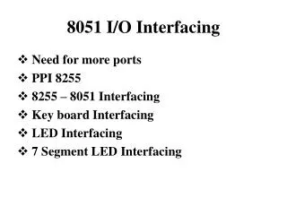
8051 I/O Interfacing • Need for more ports • PPI 8255 • 8255 – 8051 Interfacing • Key board Interfacing • LED Interfacing • 7 Segment LED Interfacing
I/O Interfacing I/O Devices connected through ports 8051 has 4 I/O ports P0 to P3. In case 8051 needs external program and/or data memory P0 and P2 are used for address bus & P0 is used for data bus. Only 2 ports (P1,P3) remain i.e. only 2 I/O devices can be connected. In case system application needs interrupt, serial I/O, i.e. alternate functions of P3 Only 1 port (P1) remain i.e only 1 I/O device can be interfaced.
In case of 8031(Rom less version ) • Program memory is external i.e. (P0 and P2) are not available for I/O interfacing. • If P3 in used for alternate functions then Only one port (P1) in available. • We need more ports. • Intel has designed programmable peripheral Interface (PPI) Intel 8255 for this purpose. • Intel 8255 PPI has 24 I/O lines distributed to four ports. • Port A – (8 Lines) • Port B – (8 Lines) • Port C – (Upper) – (4 Lines) • Port C- (Lower) – (4 Lines)
Each port can be programmed to be input or output. • Individual port lines can’t be read or written to - different from 8051 ports. • Ports have been put in two groups. • Group A - Port A and Port C (Upper) (PA7 – PA0) (PC7 – PC4) • Group B - Port B and Port C (Lower) (PB7 – PB0) (PC3 – PC0)
D7- D0 – Used for data transfer between µp and 8255 (Bidirectional) • RD (Input) - Read control Signal • WR (Input) - Write control Signal • RESET (Input)- Resets the ports. Ports are configured an input ports on Reset. • CS - Used to select the 8255 chip. Chip is selected based on the address decoding. • A1, A0 - Are used to select the specified ports in 8255. -A1. A0 are lower 2 bits of as address lines. Issued by µp
A1A0 0 0 - Port A 0 1 - Port B 1 0 - Port C 1 1 - Control Register • Note – There is no separate selection for Port C (Upper) or Port C (Lower) Port C is selected as a whole i.e. both upper and Lower ports are selected when A1, A0 = 10. • Control Register is used to program the • Ports as input or output • Program the I/O mode.
The I/O ports can be programmed to work in any of the 3 modes Mode 0 - Basic Input –Output Mode 1 - Strobed Input-Output Mode 2 - Strobed Bidirectional Bus • Mode 0 – Basic Input-Output majority of application fall under this mode. - Any port A , B, C(U) or C(L) can be input or output
Mode 1- Strobed input-output - Provides means for transferring I/O data to or from a specified port in conjunction with strobes or hand shaking signals. - Port C lines are used for hand shaking signals. - Port A and Port B can be used as input or output. - Port A uses port C (Upper) lines for hand shaking – Group A - Port B uses port C (Lower) lines for hand shaking – Group B
Mode 2- Strobed Bidirectional Bus • Port A can be used for input as well or output for transmitting as well as receiving the data in conjunction with hand shaking signals on Port C. • Hand shaking signals are provided to maintain proper bus flow direction • 5 bits (PC7-PC3) of port C are used for hand shaking. Mode 2 is available for only Group A. • Parallely Group B i.e port B can be used in mode 0 or 1. • Configuring 8255 - We have already mentioned that 8255 ports can be configured using control register (A1 A0 = 11). - The control word format for configuration of 8255 is shown
Example- We need to configure 8255 with Port A as input, Port B as output, Port C (L) as output, port C (upper) as input using mode=00
Note – Mode set flag i.e. D7=1 for all configuration. If this bit is one then only mode setting with be done by 8255. • Thus D7=1 , D5, D6=00-Mode 0, D4=1 (Port A=Input), D3=1[Port C(Upper)=Input], D2=0, (Mode=0) D1=0 (port B=output), D0=0 [ Port C(lower)=output] • So the Configuration byte = D7 D6 D5 D4 D3 D2 D1 D0 =98 H • By transferring 98H to control Register of 8255 will configure 8255 in the above manner. • How -? We shall see after interfacing of 8255 with 8051. • Note – The concept of 8255 configuration using control register has been used in 8051 in case of Timer, Serial I/O and interrupts.
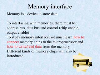
8255 – 8051 Interfacing • Let us review I/O mapped I/O and memory mapped I/O [Ref. Page 38-39 of Krishna Kant book.] • In I/O mapped I/O- The µp has separate instructions for memory and I/O read-write. • In addition µp will have separate control signals for I/O read-write and memory read-write. • A variation of this may be that µp has same read-write control signal for I/O and memory but may have another signal to identify whether the read-write is for memory or for I/O. I/O and memory are treated separately Example – 8086 has IN and OUT as I/O read and write instructions. It has same RD (for read),WR (for write), signal for I/O and memory read- write. It has M/IO to identify memory or I/O read-write.
In Memory mapped I/O • I/O ports are treated as memory locations. • µp having memory mapped I/O. • Will not have separate instructions for I/O and memory read-write. • Will have only single read and write control signals for read and write. • Will not have any signal to identify memory or I/O read-write. Example - • 8051 has no separate instructions for memory and I/O read - write • 8051 has only single read and write control signal
PSEN – external program memory read • RD – External data memory read • WR - External data memory write • It has no signal to indentify whether read - write in for I/O or memory. • Thus – I/O ports are treated as memory locations. • Thus if we have to interface 8255 to 8051 , 8255 must be interfaced in external memory • External program memory can’t be written to . • Thus 8255 must be interfaced in the external data memory. • We need to select the address ‘XXXXH’ of 8255 • The address on address lines to be decoded such that when ‘XXXXH’ is there, CS for 8255 is generated i.e 8255 needs to be selected.
RD (8051) connect to RD (8255) • WR (8051) connect to WR (8255) • Movx instructions to be used for data transfer from / to 8255 • 8255 has four ports • When address lines A1 – A0 = 00 - Port A is selected = 01 - Port B is selected = 10 - Port C is selected = 11 - Control register is selected • Thus last two bits starting address of 8255 address must be 00
Assume that 8255 is interfaced at address FE10H Port A address = FE10H Port B address = FE11H Port C address = FE12H Control register address = FE13H MOV DPTR, # FEI3H MOV A, # 98H MOVX, @DPTR, A (will configure 8255) MOV DPTR, # FE10H MOVX A, @ DPTR (will bring the content of Port A to ACC.)
To generate CS for 8255 from given address. Assume address = FE10 15 14 13 12 11 10 9 8 7 6 5 4 3 2 1 0 F E 1 0 • A1 , A0 are directly connected to 8255 and used for selection of I/O ports A,B,C and Control Regester. • For selection of 8255 through CS, the address bits A2 to A15 may be decoded using simple gates.
A15 A14 A13 A12 A11 A10 A9 A8 CS of 8255 A7 A6 A5 A4 A3 A2 Many Variations of circuits are possible
If we select 8255 address as 0030H then decoding may be- A5 A4 0 0 0 0 0 0 0 0 0 0 1 1 0 0 0 0 A7 A6 A5 A4 CS A3 A2
But it will generate Cs for 8255 for all address where A7 to A2 = 00 11 00 • i.e. 0030H, 0130H …………….FF30H • All these address will be valid for 8255 selection and are called address aliases – (aliases is used in general for other names identifying a person) Problem - 1 • If selected address for 8255 = 8000H i.e. • 1000 0000 0000 0000 • What will be decoding strategy ?
Problem -2 • If 8255 address = 1110H • Then what will be decoding • Decoder 74LS138 may also be used.
A12 A15 1 1 1 0 0 0 0 0 0 0 0 0 0 0 0 0 A1 A0 A15 A14 A13 A12 CS of 8255 A11 OR A10 A 9 A 8 Decoding of 8255 Address E000H to generate chip select
Reading and writing to 8255 ports • Let us assume that 8255 has been interfaced at address E000H the port addresses will be Port A - E000H Port B - E001H Port C - E002H Control register - E003H • Consider that the application demands the following ports configuration Port A - Output Port B - Input Port C - Output Mode = 0 What will be control word of 8255 ?
The 8255 control word will be-1000 0010 =82H We may configure 8255 by writing 82H to control register in two ways:- (A) MOV DPTR, # E003H MOV A, # 82H MOVX @DPTR,A Note - E003 is location in external data memory. Other way of writing (A) will be (B) PRA EQH E000H PRB EQH E001H PRC EQH E002H PRCR EQH E003H ORG 00H SJMP 030H ORG 030H
MOV DPTR, # PRCR MOV A, # 82H MOVX @DPTR, A • To read data from Port B MOV DPTR, # PRB MOVX A,@DPTR • To write data to Port A MOV DPTR,# PRA MOV A,# Data MOVX @DPTR, A
Note :- 8255 ports ie . A,B,C have no addressable bits. • That to find status of individual bits – • Read port context • Use logical operations ANL ORL etc Or - Use shift/rotate RRL , RRL etc • In keil bit (24 MHz, 8051) 8255 has been interfaced at addres E000H • In program (B) way of writing is normally used. • Now let us take some I/O interface • We shall first take up • Keyboard interfacing followed by • LED interfacing and • 7 segment LED interfacing
IN High OUT (High when the key is pressed) • Keyboard interfacing Basic keyboard operation is shown in figure Basic keyboard operation-single key.
OUT 1 IN OUT 2 Basic keyboard operation- two keys.
OUT 1 OUT 2 IN OUT 3 • Above Configuration can’t be adopted for more no. of keys • A 64 key keyboard will require 8 bit ports • We may represent the above as. OUT 4 Basic keyboard operation – four keys.
(1) OUT1 (2) IN1 C OUT2 (3) (4) IN2 2x2 keyboard operation
Contains two rows – IN1 and IN2 and two columns OUT1 and OUT2 • Activate Row1 i.e IN1 check OUT1 (If 1 then key No. 1) • Else cheek OUT2 (If 1 then key No. 2) • Activate Row2 i.e IN2 check OUT2 (If 1 then key No. 3) • Else check OUT2 (If 1 then key No. 4) • 8 x 8 key board can be arranged in 8 rows and 8 columns. • Only two ports are required to interface with µp.
XX1 XX2 • The codes of keys of key board may be staored row wise is memory. • When a Key is pressed. row no. and column no. i.e. position of key is identified key code is taken from table and used in the program. XX8 Code table for 8 x 8 keyboard
Keyboard- microprocessor interface software flowchart Start I 1 Enable the Ith row Set the address of the code for the first key on this row Check for key depression Determine the column number and the code of the key Key Depressed ? Yes No I I+1 No Yes I>8 ?
Key Debouncing • When a key is depressed and released contact is not broken permanently. • Key makes and breaks the contact several time for few milliseconds before the contact is broken permanently. • Thus a key depression detected by µp may be false i.e it may be due to bouncing of key. • Thus key debouncing i.e. as certaining that key depression in true is important. • Debouncing by HW and SW both in possible. • Software debouncing after key depression detected. • µp executes a delay routine for few milliseconds. • µp then again checks for key depression. • If key is depression is detected then real depression else false depression.
Let us interface 4x4 keyboard with 8051 • Both rows and columns can be connected to 8 lines of one port. • Rows can be activated by using SET B bit instruction. • Key Depression can be checked by using JB or JNB instructions. • Hex key pad interface in Lab. - 16 keys (0 to F) arranged in - 4 x 4 key board • Rows connected to – PB0 to PB3 • Columns connected to – PA0 to PA3 • You have to determine the key depression • Store the code of the key in memory.
LED Interface • LED i.eLight Emitting Diode emits light energy when conducts Anode is held at higher voltage than cathod +5 V LED operation.
[ Port bit = 1 LED Conducts i.e glows ] Port LED interface with microprocessor • Common cathode Anode connected to Port Lines All cathodes connected together to grounds Bit 7 Bit 0 Microprocessor interface to LED (common cathode)
[ Port bit = 0 LED Conducts i.e glows ] • Common Anode Anodes of all LED’s connected together to 5V Cathodes of LED’s connected to port lines Bit 7 Bit 0 +5 V Microprocessor interface to LED (common anode).
In common cathode- by making individual port bits as “1” we may glow the LED. • SETB P2.7 i.e LED connected to P2.7 will glow • MOV P2,#OFFH – All LED’s connected to port Port P2 will glow • In common Anode making a particular port bit ‘0’ will glow the LED connected to the port line. • CLR P2.7- LED connected to P2.7 will glow • MOV P2, # 00H- Will glow all the LED’s connected to port P2.
a Seven segment LED’s – The LED’s can be arranged in the fashion shownin f b g • The structure has eight segments a,b,c,d,e,f,g and h. Very use full in displaying numeric and alphanumeric data. Example :- For displaying A, all segments except d and h should glow. c e h d
Character formation in seven segment LEDs a a f b f g g c e c e d
For displaying 6, all segments except b and h should glow. • h is used for displaying decimal point. Note – Previously there were only seven segments. Eighth segment h has been added later. But name seven segment has remained stock. • The On/Off in formation of segments can be arranged in one byte. • Called control byte for 7 segment LED • The bits (port lines) can be connected to segments as common catnode or common anode fashion. Common Catnode - Anodes connected to bits catnodes connected to ground. Common Anode – Anodes connected to +5V catnodes connected to bit.
Representing segment code in byte- two ways 7 6 5 4 3 2 1 0 a b c d e f g h 7 6 5 4 3 2 1 0 h g f e d c b a 0-Glow the segment for common Anode configuration 1-Do not glow
Common Catnode - bit =1, segment glows bit = 0 – doesn’t glow Common Anode - bit = 0 – segment glows bit = 1 – segment doesn't glow • Microprocessor can be interfaced to seven segment LED in parallel or serial way.
Parallel interface +5 V Anode b a h … Resisters Out port 7 6 0 Microprocessor interface to seven-segment LED (parallel interface).
in common Anode fashion • Cathode of segments – connected to port bits. MOV Px, #00H – will glow all the segments CLR Px .3 – will glow segment No. 3 i.e segment ‘e’. • Simple Hard ware and software interface • For one 7 segment LED i.e display of 1 character one port is dedicated. • Thus for displaying 20 characters, 20 ports will be required. Generation of ports will require extra hardware. • Parallel interface is very fast but we don’t require very fast changing display due to limitation of our eyes. Serial Interface- Overcomes the limitation of parallel interface in case of large no. of 7 segment displays.