Download
1 / 35
350 likes | 372 Vues
Locking in Virgo Matteo Barsuglia ILIAS, Cascina, July 7 th 2004. Outline. Introduction: optical scheme, terms, etc… Actors: Hardware, software, simulation Results: Experience with a single arm (cavity locking, frequency stabilization, ouput-mode cleaner locking)

E N D
Locking in VirgoMatteo BarsugliaILIAS, Cascina, July 7th 2004
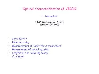
Outline • Introduction: optical scheme, terms, etc… • Actors: Hardware, software, simulation • Results: • Experience with a single arm (cavity locking, frequency stabilization, ouput-mode cleaner locking) • The recombined interferometer (almost all the controls working) • Full detector lock acquisition (preparation and first results)
Virgo optical scheme West cavity F=50 Fabry-Perot Michelson Power recycling Recycling cavity G=50 North cavity F=50 Dark fringe
Standard base • MICH = ln-lw • PRC= lrec+(lN+ lw)/2 • CARM= LN+LW • DARM=LN-LW Lw lw lrec LN lN
Intro: photodiode names 8 Transmission west • 3 signals for each photodiode: DC, ACp, Acq In- phase quadrature 7 Transmission north 5 and 5_2f 2 1 reflection Antisymetric port
Detection system InGaAs photodiodes 6.26 MHz (only 1 modulation) 16 bits ADC
Digital controls • 10 kHz sampling • VME based, homemade • software in C Photodiodes signals (DOL’s) Control signals (DOL’s) Last stage 3 for each suspension Alignment Locking trigger, signal processing, filtering
Mirror actuators Beam splitter Reference mass 4 coils 40 mN
Siesta • Real time simulation package of the Virgo experiment • Written in C, configuration cards • produces frames • Can be interfaced to the real time control system (global control)
Algorithms running in the global control Photodiodes signals Control signals Siesta SIESTA
Algorithms running in the global control Photodiodes signals Control signals Siesta VIRGO
North cavity locking Test: Locking Autoalignment Frequency stabilization tidal control north arm
m Signals and linearization Lock acquisition speed threshold ~ 10 mm/s Linearized error signal No Linearized error signal
Signals and simulation Time domain Simulation (Siesta) Correction Transmitted power
Cavity first locking • Locking at the first trial • first lock ~ 1 hour • frequency noise Transmitted power Frequency noise reduction
Lock acquisition statistics • 24 locking events collected locking and delocking the cavity • 23 lock acquisition at the first attempt, only 1 failed locking attempt
Lock acquisition statistics • Relative velocity between the mirrors computed for each locking attempt 2.5mm/s: mean value of the velocity • 8mm/s: maximum velocity for the lock acquisition success • 12.5 mm/s: velocity of the failed event Failed locking attempt v ~ 12.5 8
Cavity locking accuracy 3 picometers RMS
Sensitivity (m/Hz) Before OMC After OMC Output mode-cleaner locking 1. Cavity locked with ~ 1% of the light 2. Mode-cleaner locked 3. Control transferred to this phd ~ 99% of the light
Output mode-cleaner locking c 2 Reflected P Transmitted P 2 min Error signal State Temperature
Frequency stabilization - North cavity error signal sent to the input mode-cleaner (below 200 Hz) and to the laser (above 200 Hz) - Reference cavity error signal used to control cavity length at DC
Recombined ITF west arm north arm
Recombined ITF • Sensitivity ~ • 3 d.o.f. decoupled • fields are not mixed • lock acquisition easy • no “dynamical effects” ~ 1W (500 W) 10 W
B8_phase/B8_DC WE NE BS B2_quad B5_phase/B7_DC Lock Acquisition – Overview 3 Steps lock acquisition: • Lock of the two cavities (independently) Corrections sent to NE and WE • Lock of the michelson length Corrections sent to BS West arm North arm Michelson length
Linear Locking - Overview West arm Michelson length North arm B2_quad B1p_phase ⊗ B2_phase
Full Virgo lock acq approach • Technique choosen: use the LIGO one (developed by Evans et al.) • VIRGO and LIGO have the same optical scheme, and similar optical parameters. • VIRGO and LIGO have similar control systems (digital, quite similar sampling frequencies,…). • VIRGO and LIGO have similar simulation packages (real time, etc…) • pragmatic point of view …the LIGO approach works • Few differences between LIGO and VIRGO • Pick-off signal different • Arm finesse in LIGO = 200 (Virgo =50) • Suspension and local controls system simpler in LIGO • Reproduce the LIGO technique with SIESTA • only optics (TEMO00, no saturation, no superattenuators) • Include fine effects (saturations, etc…)
Full virgo lock acq approach • very difficult to have the 4 d.o.f. satisfied, in a linear regime • Sequencial & Statistical (the states are not stable) • used in LIGO, works well in 3 itf’s • lot of signal processing (linearization, dynamical matrix inversion) • simulation crucial central cavity locked central cavity + first arm all ITF locked
Optical characherization • parameters of the optical matix (~ 10 ) determined by simulation • very important to reproduce in simulation the optical behaviour of the interferometer • During the CITF the locking parameters (2) what dermined in this way • optical characterization is a strategic item Each element = K P(measured throughB7/B8/B5_2f)
Simulation Sidebands power inside the rec cavity Power inside the rec cavity North cavity Trans power West cavity Trans power
“step 3” locking • Lock of the central cavity (CITF) on the sidebands + lock of the north arm (on the carrier) B2_P B1_Q B2_Q
Conclusions and next steps • Experience with a single cavity and recombined very interesting to understand the hardware/software/signals/simulations • Real time simulation crucial tool (understand signals, test algos, save commissioning time) • Hardware and software tested and performant (algos in C++, parameter in a database, etc…) • This summer: try to lock the recycled interferometer and prepare linear lock and final frequency stabilization.