Preparation for Midterm
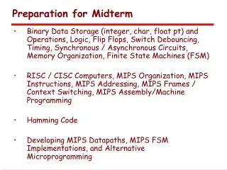
Preparation for Midterm. Binary Data Storage (integer, char, float pt) and Operations, Logic, Flip Flops, Switch Debouncing, Timing, Synchronous / Asynchronous Circuits, Memory Organization, Finite State Machines (FSM)

Preparation for Midterm
E N D
Presentation Transcript
Preparation for Midterm • Binary Data Storage (integer, char, float pt) and Operations, Logic, Flip Flops, Switch Debouncing, Timing, Synchronous / Asynchronous Circuits, Memory Organization, Finite State Machines (FSM) • RISC / CISC Computers, MIPS Organization, MIPS Instructions, MIPS Addressing, MIPS Frames / Context Switching, MIPS Assembly/Machine Programming • Hamming Code • Developing MIPS Datapaths, MIPS FSM Implementations, and Alternative Microprogramming
Preparation for Midterm • Midterm Questions/Problems will attempt to evaluate understanding of concepts and ability to use them, e.g. in design. • Review Class Slides – use them to test your understanding. Review HW assignments and Projects. • Midterm will be Closed Book, Open Minds. • Understand material on MIPS Reference Data Card. Bring it with you for the midterm. • Midterm will be designed to take approximately ½ of the period. You will have the entire period as needed.
Appendix C Mapping Control to Hardware For a Single Clock Cycle Implementation For a Multiple Clock Cycle Implementation
31 25 0 J-type: op target address Implementing the Simple MIPS Machine MIPS has 3 Instruction Types: 31 25 20 15 10 5 0 R-type: op rs rt rd shamt funct 31 25 20 15 0 I-Type: address offset op rs rt The Simple Machine Implements: R-Types: ADD, SUB, AND, OR, NOR, SLT I-Types: LW, SW, & BEQ J-Types: J
Single Cycle Datapath with Control Unit 0 Add Add 1 4 Shift left 2 PCSrc ALUOp Branch MemRead Instr[31-26] Control Unit MemtoReg MemWrite ALUSrc RegWrite RegDst ovf Instr[25-21] Read Addr 1 Instruction Memory Read Data 1 Address Register File Instr[20-16] zero Read Addr 2 Data Memory Read Address PC Instr[31-0] 0 Read Data 1 ALU Write Addr Read Data 2 0 1 Write Data 0 Instr[15 -11] Write Data 1 Instr[15-0] Sign Extend ALU control 16 32 Instr[5-0]
Generating the ALU Control Signals ALUOp1 & ALUOp2 are generated from the 6 bit OPCODE: 00 for LW & SW 01 for BEQ 10 for R-Type (ADD, SUB, AND, OR, NOR, SLT)
Generating the ALUOp1 & ALUOp0 Signals ALUOp1 & ALUOp0 are generated from the 6 bit OPCODE: Instruction Types: Instructions (Opcodes) ALUOp1 &ALUp0 R-Type: ADD, SUB, AND, OR, NOR, SLT (000000) 10 I-Type: LW (100010) & SW (101011) 00 I-Type: BEQ (000100) 01 J-Type: J (000010) XX (Doesn’t use the ALU) OpCodes | ALUOp1 ALUOp0 000000 | 1 0 100010 | 0 0 101011 | 0 0 000100 | 0 1 000010 | X X
Implementing the Multiple Clock Cycle Machine • The Multiple Cycle Machine cannot be implemented simply as combinational logic. Why? Because each instruction requires 3 -5 states (clock cycles) to complete. • It will require a Finite State machine (FSM). A set of states. How many? Combinational logic for control signals. Combinational logic for next state inputs. • It can be implemented with a PLA(s).
MDR The Multicycle Datapath with Control Signals PCWriteCond PCWrite PCSource IorD ALUOp MemRead Control ALUSrcB MemWrite ALUSrcA MemtoReg RegWrite IRWrite RegDst PC[31-28] Instr[31-26] Shift left 2 28 Instr[25-0] 2 0 1 Address Memory 0 PC 0 Read Addr 1 A Read Data 1 IR Register File 1 1 zero Read Addr 2 Read Data (Instr. or Data) 0 ALUout ALU Write Addr Write Data 1 Read Data 2 B 0 1 Write Data 4 1 0 2 Instr[15-0] Sign Extend Shift left 2 3 32 ALU control Instr[5-0]
Micro-Programmed Control An alternative to a FSM implementation. Most Computers today are at least partially implemented with Micro-program control The concept is to build a simpler internal computer (micro-computer) that implements the control sequences (micro-instructions) that are stored in a micro-computer memory (ROM) The advantage is ease of design, flexibility, and adaptability to “families of computers”. Particularly useful in CICS Machine Implementation.
Control Unit Organization The Control Memory contains sequences of microinstructions that provide the control signals to execute instruction cycles, e.g. Fetch, Indirect, Execute, and Interrupt. • Tasks of Control Unit: • Microinstruction sequencing • Microinstruction execution
Horizontal Micro-programming • Wide control memory word • High degree of parallel operations possible • Little encoding of control information • Relatively Fast
Vertical Micro-programming • Word width can be much narrower • Control signals encoded into function codes – need to be decoded • More complex, more complicated to program, less flexibility • More difficult to modify • Slower
Next Address Decision ? • Like a normal computer, we want to allow branches. Why? • Target address depends upon “ALU flags” and control buffer register bits: Get next instruction • Add 1 to control address register Jump to machine instruction routine • Load control address register based on opcode in IR Jump to other new routine based on jump microinstruction • Load address field of control buffer register into control address register
Branch Control: Two Address Fields • Branch based upon: • Instruction Opcode • Address 1 • Address 2 • Does require a wide microinstruction, but no address calculation is needed
Branch Control: Single Address Field • Branch based upon: • Next instruction • Address • Opcode • Does require more • circuitry, e.g. adder
Branch Control: Variable Format • One bit determines microinstruction format: • Control signal format • Branch format • Does require even more circuitry, and is slowest.
Reflection on Microprogramming Control • The advantage is ease of design, flexibility, and adaptability to “families of computers”. • The disadvantage is speed. • Particularly useful in CICS Machine implementation, since they have a lot of complex instructions and hence complex design requirements. • One of the advantages of RISC machines is that they intrinsically simple and don’t need a lot of complex options and huge numbers of states to implement. • In reality, our view of the MIPS RISC machine is distorted by the simplicity of the subset of the MIPS machine that we looked at.