Central Processing Unit (CPU)
Central Processing Unit (CPU). CPU is the heart and brain It interprets and executes machine level instructions Controls data transfer from/to Main Memory (MM) and CPU Detects any errors In the following lectures, we will learn: Instruction representation

Central Processing Unit (CPU)
E N D
Presentation Transcript
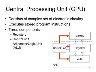
Central Processing Unit (CPU) • CPU is the heart and brain • It interprets and executes machine level instructions • Controls data transfer from/to Main Memory (MM) and CPU • Detects any errors • In the following lectures, we will learn: • Instruction representation • Data transfer mechanism between MM and CPU • The internal functional units of two different CPU architectures • How these units are interconnected • How a processor executes instructions
Instruction Representation • CPU operation is determined by the instruction it executes • Collection of these instructions that a CPU can execute forms its Instruction Set • An instruction is represented as sequence of bits, for example: • Instruction is divided into fields • Opcodeindicates the operation to be performed, eg., 92 above indicates a copy operation – we need two operands – one source and other destination • Opcode represents • nature of operands (data or address), operand 1 is address and operand 2 is data • mode (register or memory), operand 1 is memory, and operand 2 is immediate data
Basic Instruction Types Not all instructions require two operands • 3-address instructions Operation Source1, Source2, Destination e.g. Add A, B, C ; C = A + B • 2-address instructions Operation Source, Destination e.g. Move B, C ; C = B Add A, C ; C = C + A Here Source2 is implicitly the destination • 1-address instructions e.g. Load A Store C • 0-address instructions e.g. Stop
Simple Instruction Set Assume we have a processor whose Instruction Set consists of four machine language instructions • Move from a memory location to a data register in CPU • Move from a data register in CPU to a memory location • Add the contents of a memory location to a data register • Stop Suppose our program for Z = X + Y looks like: Move X, D0 Add Y, D0 Move D0, Z Stop This program is coded into machine instruction and suppose is loaded into memory starting at location $0000 0000 $0000 0000
How does the CPU know which instruction to execute? • There is a dedicated register in CPU called Program Counter (PC) that points to the memory location where next instruction is stored Therefore, at start PC = $0000 0000 • Instruction is in Main Memory – it is to be transferred (fetched) to CPU to be executed • CPU has an Instruction Register (IR) that holds the instruction • What kind of instruction is to be executed? • CPU has its own Instruction Interpreter (Decoder) • Followed by Instruction execution • Next instruction follows. PC is incremented by length of instruction just completed
Mechanism of Transferring Data from MM to CPU CPU has an external bus that connects it to the Memory and I/O devices. The data lines are connected to the processor via the Memory Data Register (MDR) The address lines are connected to the processor via the Memory Address Register (MAR) • Memory address from where the instruction/data is to be accessed is copied into MAR • Contents of MAR are loaded onto address bus • Corresponding memory location accessed • Contents of this location put onto data bus • Data on data bus loaded into MDR Address bus MAR Data bus MDR Control bus R/W MM CPU
CISC and RISC Reduced Instruction Set Computers (RISC) • Performs simple instructions that require small number of basic steps to execute (smaller S) • Requires large number of instructions to perform a given task – large code size (larger N) • more RAM is needed to store the assembly level instructions • Advantage: Low cycles per second – each instruction is executed faster in one clock cycle (smaller R) • Example: Advanced RISC Machines (ARM) processor Complex Instruction Set Computers (CISC) • Complex instructions that involve large number of steps (larger S) • Fewer instructions needed (smaller N) – small code size • Commands represent more closely to high-level languages • Less RAM required to store the program • Disadvantage: High cycles per second • Example: Motorola 68000 processor, Intel x86
General Purpose Register (GPR)Architecture Its functional units are: Data Registers: D0, D1, D2,..., D7 for arithmetic operations – holds any kind of data Address Registers: A0, A1, A2,..., A7 serve as pointers to memory addresses Working Registers: several such registers – serve as scratch pads for CPU Program Counter (PC) holding the address in memory of the next instruction to be executed. After an instruction is fetched from memory, the PC is automatically incremented to hold the address of, or point to, the next instruction to be executed. Instruction Register (IR) holds the most recently read instruction from memory while it is being decoded by the Instruction Interpreter. Memory Address Register (MAR) holds the address of the next location to be accessed in memory. Memory Buffer Register (MBR or MDR) holds the data just read from memory, or the data which is about to be written to memory. Buffer is referring to temporarily holding data. Status Register (SR) to record status information
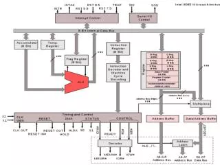
GPR CPU Register File 0 1 2 3 Data bus MBR IR Address bus MAR Interpreter ALU PC Memory Control 16 bit Increment CPU 8 bit Memory
Program Execution Fetch Cycle: • Processor fetches one instruction at a time from successive memory locations until a branch/jump occurs. • Instructions are located in the memory location pointed to by the PC • Instruction is loaded into the IR • Increment the contents of the PC by the size of an instruction Decode Cycle: • Instruction is decoded/interpreted, opcode will provide the type ofoperation to be performed, the nature and mode of the operands • Decoder and control logic unit is responsible to select the registers involved and direct the data transfer. Execute Cycle: • Carry out the actions specified by the instruction in the IR
Execution for add D1,D2 in a GPR processor MAR PC 1 MDR M[MAR] 2 Fetch PC PC + 2 3 IR MDR 4 Interpret Decode 5 6 D2 D1 + D2 Execute
GPR CPU Register File 0 1 2 3 Data bus 4 MBR 2 IR 6 5 Address bus 6 6 MAR 2 Interpreter ALU 5 1 PC Memory Control 3 16 bit Increment CPU 8 bit Memory
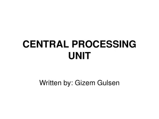
Execution for add X,D0 in a GPR processor MAR PC 1 MDR M[MAR] 2 Fetch 3 PC PC + 2 IR MDR 4 Interpret Decode 5 Address X extracted from IR MAR IR (X) 6 Contents of Address X transferred to MDR Execute 7 MDR M[MAR] Contents of Address X added to D0 8 D0 MDR + D0
GPR CPU 8 Register File 0 1 2 3 Data bus 4 MBR 7 2 IR 8 5 Address bus 8 MAR 7 2 Interpreter ALU 6 5 1 PC Memory Control 3 16 bit Increment CPU 8 bit Memory
Instruction Execution Time Clock Cycles (P) – regular time intervals defined by the CPU clock Clock Rate, R = 1/P cycles per second (Hz) 500 MHz => P = 2ns 1.25 GHz => P = 0.8ns For each instruction: Fetch: Total 12 clock cycles MAR PC 1 MDR M[MAR] 10 IR MBR 1 Decode: 2 clock cycles Execute: depends on instruction
Accumulator (Acc)Architecture • Its functional units are same as GPR architecture, except there is only ONE register – accumulator (Acc) – instead of the Register File Ex: Z = X + Y Move contents of location X to Acc Add contents of location Y to Acc Move from Acc to location Z Stop • All operations and data movements are on this single register • Most of the instructions in the instruction set require only one Operand • Destination and Source are implicitly Acc • Leads to shorter instructions but program may be slower to execute since there are more moves to memory for intermediate results (to free Acc) • May lead to inefficiency
Accumulator ArchitectureCPU Acc Data bus MBR IR Address bus MAR Interpreter ALU PC Memory Control 16 bit Increment CPU 10bit Memory
Execution for Add Y in an Acc Architecture MAR PC 1 MDR M[MAR] 2 Fetch 3 PC PC + 2 IR MDR 4 Interpret Decode 5 Address X extracted from IR MAR IR (X) 6 Contents of Address X transferred to MDR Execute 7 MDR M[MAR] Contents of Address X added to Accumulator 8 Acc MDR + Acc
GPR vs AccLet the following instructions be allowed: For Accumulator machine Add x ; Sub x ; Multx ; LD x ; ST x ; Stop Note that For GPR machine (with 4 data reg) • Move , ; Move , M[X]; Move; • Add , M[X]; Add , ; • Sub , M[X] ; Sub , ; • Mult, ; • Stop
GPR vs AccAssembly Program for a <- (x + y) * (x – y) For Accumulator machine LD X ADD Y ST C LD X SUB Y MULT C ST A STOP For GPR machine (with 4 data reg) Move Add Move Sub Mult Move Stop