Quasi Static Testing
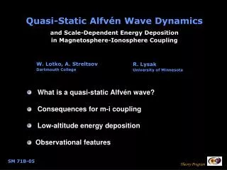
Quasi Static Testing. Advanced Quasi-Static Testing Technology and Applications. Henry Patland 2192 Bering Drive San Jose, CA 95131 hpatland@us-isi.com www.us-isi.com. Topics. Introduction to Quasi-Static Testing Advanced Quasi-Static Testing Technology Quasi-Static Testing Applications.


Quasi Static Testing
E N D
Presentation Transcript
Quasi Static Testing Advanced Quasi-Static Testing Technology and Applications Henry Patland 2192 Bering Drive San Jose, CA 95131 hpatland@us-isi.com www.us-isi.com
Topics • Introduction to Quasi-Static Testing • Advanced Quasi-Static Testing Technology • Quasi-Static Testing Applications
QST Testing as a Concept Quasi Static Testing can characterize the GMR/TMR performance, with the following advantages over DET Testing: • Independent of external influence (disk/flying height variation) • Significantly more flexible, with the ability to subject the GMR/TMR to any variety of ambient conditions. • Can analyze pure GMR/TMR performance with higher resolution than DET Testing. • Reduced Risk of Handling or Tester damaging heads • QST Testing is inexpensive, fast, relatively simple, and requires significantly lower maintenance and operating costs.
Basics of Quasi-Static Testing The roots of QST are derived from actual drive operation As GMR/TMR passes over a disk it is introduced to a variety of magnetic field. In simplest terms the resistance of the GMR/TMR is dependent on the magnetic field applied to it. In ideal case the relationship of GMR/TMR resistance to applied field is linear, but we don’t live in ideal world. Close To Ideal Transfer Curve
Transverse Transfer Curve Parametrics extracted from QST Transfer Curve
DC Measurements Measures head resistance change versus an externally applied magnetic field through a low frequency channel. The following DC tests can be performed. Transfer curve Stability Bias angle Asymmetry sweep Resistance delta Quasi-Static test
Static Tests (HSA / HDA) Verification of the Preamp Chip, Flex, and Voice Coil assembly can be performed. Voice coil measurements Fault detection Current consumption Pin-Pin and Pin-Ground shorts Temperature Sensor control Passive component measurements RDX / RDY offset voltage
AC Measurements Measures high frequency noise as influenced by write excitation, field excitation, or combinations of both. The following AC tests can be performed Popcorn Noise W/R Recovery Field Induced Noise Characterization Frequency Response
AC Channel Technology • Glitch After Write (Popcorn) • Field Induced Instabilities (Noise) • Spectral Analysis (FFT) • 200 Mhz Analog Bandwidth • 160 Mhz 10-bit digitizer • Low Noise • W/R Recovery < 500 ns • 400 Mhz Write Frequency
Write Induced Instabilities Writer Induced Instabilities (Popcorn)
Field Induced Instability Soft Kink at 160 Oe
Spectral Maximum Amplitude Noise Noise RMS (uV) Noise Amp (uV) Max Noise Amp (uV) S.M.A.N
Digitizer is The Key to S.M.A.N. • Qualifies Three Types of Instability Events in One Shot • RMS Noise for broadband noise • Max Amp for rare events such as Barkh. Jumps and Write Induced Instability • Amp Noise for high probability noise
Transfer Curve & S.M.A.N. Soft Kink and Max Noise at 160 Oe
Applications for QST Testing • Bar, Slider Testing • HGA, HSA, HDA Testing • ESD Tolerance Testing • Thermal Reliability Testing
Benefits of Row/Slider Testing • Early look at Wafer process for QST Parametrics and Instability • Upstream testing reduces scrap cost • Bar to 4000 Sliders/Hour • Slider to 1200 Sliders/Hour
HGA, HSA, HDA Level Testing HGA HSA HDA
Benefits of HGA, HSA, HDA Testing • Process Control • Simple Test/Tooling • Failure Analysis at HDA level • HSA Screening Prior to Drive Build • HDA Screening After Servo Write
ESD Tolerance Measurement And Process Mapping • ESD Tolerance: Repetitive “Inject and Test” HBM, MM and DCDM • CDM (Charged Device Model) is rapidly becoming the standard for characterizing GMR/TMR head ESD Failure Thresholds • Process Mapping: Test After Each Process Including Bar, Slider, HGA (Before/After DET), HSA Prior to Final Bond and HDA After Merge and After Servo Write • Symptoms: First Failure Mode: Instability, then Parametrics
CDM Tolerance Characterization D-CDM Cartridge Assembly ESD/CDM Pulse System
Sensor Damage Multiple distributed melting points HBM: 10% Resistance Change CDM: 100% Resistance Change QST can characterize ESD damage by applying controlled ESD events to GMR head HBM CDM
What can be done about GMR/TMR head ESD Sensitivity ? • Improved design of GMR/TMR head which is less sensitive to ESD • Eliminate ESD events from Manufacturing • Monitor GMR/TMR head performance after every significant process to isolate and eliminate ESD events in Manufacturing As Al Wallash – Maxtor would put it: “Don’t loose your head over ESD” Whatever you do, QST Testing can Help!
By Applying Varying Amplitude ESD Events to GMR Head, QST can easily determine heads Failure points Resistance Failure Meltdown Amp Failure Pin Reversal Asymmetry Failure
DCDM Sweep CDM Failure Threshold at 3.5V 25% lower than Amp Failure at 5V
Thermal Reliability Testing • Accelerated Life Testing at Row Level • Accelerated Life Testing at HGA Level
Accelerated Life Test @ 5.5 Days Resistance and Amplitude Deteriorating after 5.5 Days of elevated temperature (100C) and elevated VBias
HGA Level Accelerated Life Test Up to 8 simultaneous HGA testing
Parametrics vs. Temperature Temperature Test Transfer Curve
Benefits of Thermal Reliability Testing • Accelerated Life Testing Can Predict Failures Before They Occur • Row Level Testing Provides Early Look at Thermal Reliability
Conclusion Don’t loose your head over ESD, Instability or Reliability Whatever you do, QST Testing can Help!
References [1] J.Himle, R.Cross, M.Greenwell, “Drive-Level Instabilities Correlated to Quasi-Static Field Testing”, MMM-Intermag 2001 [2] C. Moore, “A Comparison of Quasi-Static Characteristics and Failure Signatures of GMR Heads subjected to CDM and HBM ESD Events” [3] H. Patland, W. Ogle, “High Frequency Instabilities in GMR Heads Due to Metal-To-Metal Contact ESD Transients”, EOS/ESD Symposium 2002 [4] Integral Solutions Int’l, “Quasi 97” and “QST-2002” Tester
Acknowledgements • Al Wallash –Maxtor • Mark Nichols –Maxtor


![Magnetic quasi-static simulation [coreless liquid-cooled motor]](https://cdn1.slideserve.com/1702930/slide1-dt.jpg)