Download
1 / 25
750 likes | 2.4k Vues
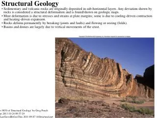
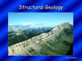
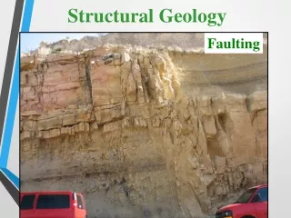
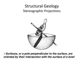
Structural Geology Stereographic Projections. Surfaces, or a pole perpendicular to the surface, are oriented by their intersection with the surface of a bowl. The stereonet grid is used as a protractor, and in structural geology, it is used to plot attitudes of planes and lines.

E N D
Structural Geology Stereographic Projections • Surfaces, or a pole perpendicular to the surface, are oriented by their intersection with the surface of a bowl
The stereonet grid is used as a protractor, and in structural geology, it is used to plot attitudes of planes and lines. The Stereonet Grid.
The stereonet grid is a protractor which can measure strike and dip, and trend (bearing and and plunge) – the attitude of lines and planes. Since the equatorial plane is horizontal, its edge (called the primitive great circle) measures the strike or bearing. The great circles can measure dip or plunge. Plotting Planes using the Stereonet Grid.
Plotting Planes using the Stereonet Grid. Plotting is done on transparent paper laid over the stereonet that can be rotated around a thumb tack poking up at the center of the net. A tick mark coinciding with the 0 on the primitive circle is labeled N. E, S and W occur at 90, 180 and 270o respectively.
Suppose a sandstone layer has strike and dip N80W 40S 1: Plotting a Plane using the Stereonet Visualize the plane in space and the way it cuts the sphere.
Place the overlay on the net and mark N, S, E, & W on the overlay. The layer is N80W, 40S Plotting a Plane using the Stereonet With the overlay positioned with N at 0o, Count 80o CCW to N80W and place a tick mark showing the position of the strike.
The layer is N80W, 40S Next, rotate the transparency so the strike is at 0. Now you can find the great circle with the same dip (40) as the layer by counting 40 from the primitive circle along the 90 – 270 diameter. Make sure you count in from the primitive along the equator Now trace that great circle on the transparency and you have the projection of the layer plotted. Plotting a Plane using the Stereonet
The layer is N80W, 40S Plotting a Plane using the Stereonet Now, rotate the transparency back so North on the transparency coincides with 0 on the stereonet. The plot now shows the projected position of the layer in space.
The line is a fold axis at bearing S42W, plunge angle 38o Visualize the line in space plunging 38o to the SW 2: Plotting a Line using the Stereonet
The line is a fold axis at S42W, 38o Plotting a Line using the Stereonet Next, place the overlay on the net and mark N, S, E, & W on the overlay. Locate S42W and make a tick mark at that position on the primitive circle.
The line is a fold axis at S42W, 38o Next, rotate the tick mark to either of the straight line axes of the net. Measure 38o along the line from the primitive circle and put a dot. This is the projection of the point where the line penetrates the sphere. Plotting a Line using the Stereonet
The line is a fold axis at S42W, 38o Plotting a Line using the Stereonet Finally, rotate the transparency so that North coincides with 0 on the stereonet. Check to make sure your dot is in the SW quadrant.
The plane (cleavage) is N70W 43 SW or (290, 43) The line (a mineral lineation) bears S20E or 160. Plot the plane and the line and find the plunge of the line. 3: Plotting a Line on a plane Visualize the problem: A plane (cleavage) with a line (lineation) lying in the plane.
The plane (cleavage) is N70W 43 SW or (290, 43) The line bears S20E Plotting a Line on a plane Plot the plane on the overlay: Put a mark at 290
The plane (cleavage) is N70W 43 SW or (290, 43) The line has bearing S20E = 160o Plotting a Line on a plane Next rotate the overlay to 0 or 180, then count in 43o along the equator to find the great circle that dips 43o to the SW. Trace the arc.
The plane (cleavage) is N70W 43 SW or (290, 43) The line has bearing S20E = 160o Plotting a Line on a plane Rotate the overlay so that N is at 0. Mark the primitive at the bearing of the lineation, 160o.
The plane (cleavage) is N70W 43 SW or (290, 43) The line has bearing S20E = 160o Rotate the overlay so that the 160o mark is at the 0-180 axis of the net. The line from the center of the net to the 160 mark is the trend of the lineation. Where that trend line intersects the arc of the plane is the projection of the lineation that lies in the plane. The plunge on the lineation is measured from the primitive to the point on the arc. Plotting a Line on a plane
The plane (cleavage) is N70W 43 SW or (290, 43) The line has bearing S20E = 160o We plotted the plane and the line. Rotate the transparency so the plane lies along a great circle. The rake is the angle measured from the primitive along the great circle, here 58o. b. Return the Transparency to North = 0o The Rake of a Line on a plane
The attitude of a dike is 205, 65 (N25E, 65SE). What is its apparent dip on a vertical quarry wall trending 350? Visualize the problem (a) and plot the dike (b) 4: Apparent Dip knowing True Dip
The attitude of a dike is 205, 65 (N25E, 65SE). What is its apparent dip on a vertical quarry wall trending 350? Plot the quarry wall [c]. The intersection of the dike with the wall defines a line parallel to the apparent dip. Apparent Dip knowing true dip
The attitude of a dike is 205, 65 (N25E, 65SE). What is its apparent dip on a vertical quarry wall trending 350? d. Rotate the transparency so the wall is along the axis. The apparent dip angle is from the primitive to the intersection, 52o. Apparent Dip knowing true dip
Question: A layer intersecting a road cut trends 256, 32. The same layer intersects the road cut around a bend and trends 125, 27. What is the strike & dip of the layer? Visualize the problem (a) and then plot the intersections for the road cuts and the layer (b & c) True Dip from two Apparent Dips Mark 125, rotate it to vertical Count in apparent dip 27o Mark 256, rotate it to vertical Count in apparent dip 32o
Question: A layer intersecting a road cut trends 256, 32. The same layer intersects the road cut around a bend and trends 125, 27. What is the strike & dip of the layer? Because the two road cut intersections lie on the dike, rotate the transparency so the two points line on the same great circle (d). Draw the great circle. True Dip from two Apparent Dips
Question: A layer intersecting a road cut trends 256, 32. The same layer intersects the road cut around a bend and trends 125, 27. What is the strike & dip of the layer? That great circle is the attitude of the dike; measure its dip along the equator from the primitive to the great circle (d). Now rotate the transparency so that its N coincides with 0 on the net. Measure the strike and note its dip direction (e), here about N77W 54S True Dip from two Apparent Dips