Download
1 / 1
10 likes | 151 Vues
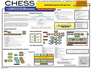
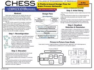
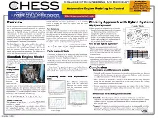
Toyota Test Cell, UCB. mass flow rates of the manifold; and is a function of the throttle angle , the pressure influence PRI, intake manifold pressure, Pm, atmospheric pressure, Pa, engine displacement, Ve, intake manifold volume, Vm, engine speed, , and volumetric efficiency, :.

E N D
Toyota Test Cell, UCB mass flow rates of the manifold; and is a function of the throttle angle , the pressure influence PRI, intake manifold pressure, Pm, atmospheric pressure, Pa, engine displacement, Ve, intake manifold volume, Vm, engine speed, , and volumetric efficiency, : Manifold intake air flow Friction Torque Engine Torque Karl Hedrick Tomoyuki Kaga Edward A. Lee Pannag R Sanketi Jose Carlos Zavala Jurado Haiyang Zheng Automotive Engine Modeling for Control http://chess.eecs.berkeley.edu Overview The development of control systems requires extensive use of models to represent the behavior of a physical plant. In particular, automotive systems can be expressed as hybrid systems in different modeling environments. In this presentation, we describe an automotive engine model created in Simulink and further present an engine model created in Ptolemy, outlining advantages and disadvantages of the models and the respective modeling environments. The final objective of this engine model is the synthesis of a controller, which would eventually be implemented on experimental facilities. The model must be accurate over the operating ranges of its inputs and be as simple as possible. The simplicity of model aids the development of control laws. Simulink Engine Model Ptolemy Approach with Hybrid Systems retard influence on torque production. cT is a constant which is roughly the same for engines with the same compression ratio. Fuel Dynamics Fueling delays are important to the overall in-cylinder air fuel ratio. When fuel is injected into the intake ports, part of the fuel deposits on the intake manifold as a liquid, part of the fuel vaporizes, and part of the fuel becomes droplets. A portion of the fuel deposited on the intake manifold wall will later enter the air stream and affect the in-cylinder air-fuel ratio. A model of these dynamics is given by Why hybrid systems? Hybrid systems are a natural way to describe the modal behavior of automotive dynamics and the corresponding control laws. For example, the ignition controller has to delicately control the spark timing of each cylinder of an engine at different operation modes, such as to achieve the best usage of fuel or to limit the HC emission. How to use hybrid systems? ( is thepart of the fuel that enters the cylinder directly as vapor) Hybrid systems are modeled with ModalModels, such that continuous-time models are hierarchical nested with Finite State Machine as the middleware to activate and deactivate certain models. (Taken from Jay Barton’s Thesis) • Performance Criteria • Accuracy, for a given set of inputs and initial conditions, we would like to know how similar the behavior of the model with respect to the physical engine is • Utilized resources. What is the execution time and what resources are required to simulate the model and execute the control law • Correctness. The question to answer is whether there is any tool inside the model or the modeling environment that detects flaws in the execution of the simulation Ptolemy provides an operational semantics for simulating hybrid systems, which gives a well-defined and deterministic behavior for complex interactions between simultaneous events and continuous dynamics. We present here a mean value model that comprises states for the air flow, fuel flow and rotational speed of the engine. It is particularly suitable for fuel injection control. Start-up phase accounts for - Most of HC emission - Considerable calibration effort Conclusion Principal Subsystems • Comments on differences in models • Simulink model assumes the existence of a throttle angle controller and does not consider throttle dynamics at present, whereas the Ptolemy model associates second order dynamics with the throttle angle. • Intake manifold air submodel is similar in both the models, the only difference being that the Simulink uses manifold air as the state, whereas the Ptolemy model uses manifold pressure as the state. • Torque generation in Simulink is mean-value and simple. One in the Ptolemy model is event-based and complex, taking into account the torque produced by each cylinder separately. • Differences in Modeling Environments • Simulink:1. Well developed software structure to interface to an embedded controller 2. Control libraries a part of the software 3. Does not support Hybrid systems very well. Can give non-deterministic delays in stateflow systems. 4. Easy user interface. • Ptolemy:1. Synthesis of embedded controllers needs to be developed 2. Good for modeling event based systems 3. More control libraries need to be developed. 4. Theory for developing controllers for hybrid systems is still under development. Air Intake The mass air flow through the intake manifold is the difference between the intake and exit Comparing model with experimental data For different subsystems, plots with the differences between the model results and the experiment results are shown. Torque Production The indicated torque, Ti, is modeled as a scaled function of the mass of air per cylinder where AFI() is the normalized air-fuel ratio influence on torque production and SPI() is the normalized spark advance or November 18, 2004