Optical System Design
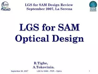
Optical System Design. N. Geis MPE. Telescope. Entrance Optics -- chopper -- calibration optics. Bolometer. Spectrometer. Field splitter. To Slicer. Bolometer Optics. Image Slicer. Grating Spectrometer. Dichroic. Anamorphic System. Dichroic. Bolometer Optics. Bolometer Optics.

Optical System Design
E N D
Presentation Transcript
Optical System Design N. Geis MPE Optical System Design
Telescope Entrance Optics -- chopper -- calibration optics Bolometer Spectrometer Field splitter To Slicer Bolometer Optics Image Slicer Grating Spectrometer Dichroic Anamorphic System Dichroic Bolometer Optics Bolometer Optics Filter Filter Wheel Filter Filter Wheel Red Bolometer Array Blue Bolometer Array Red Photoconductor Array Blue Photoconductor Array Pacs Optical System Overview Optical System Design
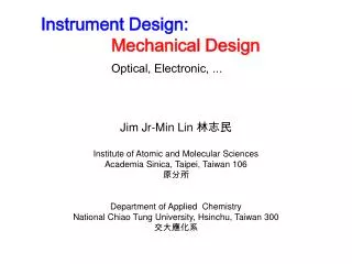
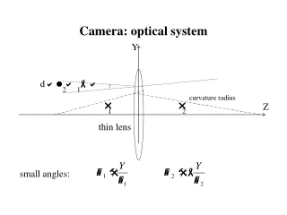
Definition of Image Scale Optical System Design
Optical Design – Top Optics • Optical design for astronomical optical path • Image inverter (3 flats) at the beginning to compensate for telescope image tilt • Chopper assembly on outer side of FPU (servicing) • Labyrinth configuration for baffling (see straylight analysis) • Chopper throw (on sky) reduced to 1 full array size to allow for larger FOV of bolometers with same entrance field-stop/mirror sizes as previous design. Optical System Design
Optical Design – Top Optics • Optical design for calibration sources • Acceptable image quality of pupil • Köhler-type illumination (pupil on source aperture + a field stop) • Source aperture is projected onto M2/Cold Stop • No physical match in source for “field” stop => excellent uniformity expected • Re-use of existing entrance optics mirrors in reverse • Excellent baffling situation • Sources are outside of Instrument Cold Stop • Initial calibration path & field stop outside of Instrument Cold Stop Optical System Design
Uniformity of Illumination by Calibrators The two sources produce mirrored illumination distributions, as seen from the detectors Maximum (unwanted) modulation of the calibration signal by non-uniformity is ~ 5% Compatible with the goal of having relative signal changes of 10% when chopping. E.g., one could set operating points such that the range of signal is 7.5–12.5% when chopping. Optical System Design
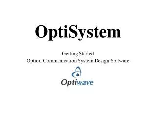
Telescope TO Fold 1 TO Fold 2 TO Fold 3 TO Active 1 Lyot Stop TO Active 2 TO Active 3 Pupil Field TO Fold 4 Chopper TO Active 4 TO Active 5 Common Focus, Top Optics Top OpticsAstronomical Optical System Design
Telescope C2 Active 3 C1 Active 3 Cal. Source 1 Cal. Source 2 TO Fold 1 C1 Active 1 (Lens) C2 Active 1 (Lens) TO Fold 2 C1 Active 2 C2 Active 2 TO Fold 3 TO Active 1 Calibrator 1 Calibrator 2 Lyot Stop TO Active 2 TO Active 3 Pupil Field TO Fold 4 Chopper TO Active 4 TO Active 5 Common Focus, Top Optics Top OpticsCalibration Optical System Design
Common Focus Top Optics Spectrometer S Collimator 1 S Collimator 1 B Active 1 S Fold 1 S Collimator 2 S Collimator 2 Dichroic Beamsplitter S Active 1 Grating S Active 2 S Fold 2 B Fold R1 B Fold B1 S Fold 3 Slicer Optics B Active R1 B Active B1 S Fold 4 B Active R2 B Active B2 S Active 3 Filter Filter Wheel S Active 4 Red Bolometer Array Blue Bolometer Array Pupil S Active 5 Field S Active 6 Dichroic Beamsplitter Filter Filter Wheel S Fold 5 Red Spectrometer Array Blue Spectrometer Array Optical componentsafter Top Optics Photometer Optical System Design
Optical Design – Photometers • Optical design for bolometer cameras finished • very good image quality • good geometry • excellent baffling situation • fully separate end trains • extra pupil and field stops possible on the way to detectors (use for alignment and baffling purposes) • exit pupil with filter at entrance window to cold (1.8K) detector housing • Bolometer arrays mounted close together on top of cryocooler • Photometers are a self-contained compact unit at FPU external wall Optical System Design
Optical Design – Spectrometers • No Changes in optical design for spectrometer since IIDR • ILB column • Slicer output was reconfigured such that one pixel’s worth of space is intentionally left blank between slices at the slit focus and on the detector array • Reduces (diffraction-) cross-talk • helps with assembly of detector filters & alignment gap of 0.75 mm between slit mirrors gap of 3.6 mm between detector blocks for filter holder • Image quality diffraction limited • Excellent baffling situation • end optics for both spectrometers separated on “ground floor” • exit field stop of spectrometer inside a “periscope” • extra pupil and field stops possible in end optics (alignment, baffles) Optical System Design
The Image Slicer Optical System Design
Image Slicer and Grating (in) Slit Mirror Slicer Mirror Capture Mirror Grating Optical System Design
Image Slicer and Grating (in+out) Slit Mirror Periscope Optics Capture Mirror Slicer Stack Grating Optical System Design
Optical Design Summary • Clean separation between optical paths – a result of the incorporation of the bolometers. • Realistic accommodation for mechanical mounts. • Significant savings in number of mirrors from the photoconductor-only design • Excellent image quality in both, photometers, and spectrometers Optical System Design
PACS Envelope -filled Optical System Design
PACS Optical Functional Groups Optical System Design
Photometer Optics Filter Wheel I Slicer Optics Blue Bolometer 0.3 K Cooler Red Bolometer Grating Grating Drive Encoder sGeGaDetector Red Spectrometer Spectrometer Optics Chopper Calibrator I and II Calibrator Optics sGeGa Detector Blue Spectrometer Filter Wheel II Entrance Optics Optical System Design
Entrance Optics & Photometer Chopper Lyot Stop Telescope Focus Dichroic Calibrator I+II FilterWheel Blue Bolometer Cryocooler Red Bolometer Optical System Design
Chopping Left Optical System Design
Chopping Right Optical System Design
The Spectrometer Section Optical System Design
PACS Filter Scheme Optical System Design
Filter Rejection Requirements(determined from template observation scenarios) • The requirements from 3 demanding astronomical scenarios... • planet with high albedo • deep imaging (Galactic/extragalactic) • FIR excess around bright star • ...lead to the required filter suppression factors. • Solid red line: total required suppression • Dashed blue line: model detector responsivity (bolometers only) Suppression factor detector response filter transmission overall response Dotted green line: resulting required filter suppression factor Wavelength [µm] Optical System Design
PACS Filters • Filter Functions • definition of spectral bands • photometric bands • order sorting for spectrometer grating • in-band transmission (high) • out-of-band suppression (thermal background, straylight, astronomical) • Filter implementation • Filter types (low-pass, high-pass, band-pass, dichroic) • Technology: Metal mesh filters developed at QMW • Proven technology • Robust • Excellent Performance • Filter location in optical path chosen for • rejection of thermal radiation from satellite • instrument stray light management Optical System Design
PACS Filtering Scheme Optical System Design
Examples of QMW filters Example: Prototype of Long Pass Edge filter Examples of QMW filters Optical System Design
Example Filter Chain: Long-Wavelength Photometer Dichroic beam splitter130.µm Long-pass edge filters 52.µm 110.µm 125.µm Short-pass edge filter 210.µm Optical System Design
Filter Summary • Filter scheme with 4 or 5 filters in series in each instrument channel provides sufficient out-of-band suppression • Measured/expected in-band transmission • > 80 % for long-pass and dichroic filters • ~ 80 % for band-pass filters • > 40 % for filter combination • ~ 50 % expected • Requirements will be met Optical System Design
Geometrical Optics Performance Optical System Design
Optical Performance - Blue Bolometer Optical System Design
Optical Performance - Geometry Blue Bolometer 3 2 1 Optical System Design
Optical Performance - Red Bolometer Optical System Design
Optical Performance - Geometry Red Bolometer Optical System Design
Optical Performance - Spectrometer Center of Array, center l Corner of Array, extreme l Optical System Design
Optical Performance - Geometry Spectrometer 174.6 µm 175.0µm 175.4µm 75% Strehl @ 80 µm 90% Strehl @ 80 µm “ILB” Optical System Design
New Req? New Goal? PACS Optical Performance in a System Context Optical System Design
Diffraction Optical System Design
2 Strategiesdepending on outcome of system straylight analysis • M2 as system stop (baseline):oversize cold stop by ~ 10% area (if only cold sky visible beyond M2, and straylight analysis allows) • Lyot stop as system stop (optional):undersize cold stop by ~ 10% area — throughput loss(if diffracted emission/reflection from M2 spider, M2 edge, or straylight is problematic) Intensity (arb. units) Radius [cm] Illumination of Lyot Stop • M2 is system aperture • Image quality of M2 on Lyot stop determined by diffraction from PACS entrance field stop • Diffraction ring ~10% of aperture area • Cannot block “Narcissus effects” from M2 center at Lyot stop without throughput loss GLAD 4.5 diffraction analysis l=175 µm Optical System Design
Diffraction Analysis - Slicer/Spectrometer • Diffraction Analysis of the Spectrometer repeated with final mirror dimensions and focal lengths, and for a larger range of wavelengths. • The results were used • as inputs to a detailed grating size specification • for optimizing mirror sizes in the spectrometer path => Diffraction on the image slicer leads to considerable deviations from the geometrical footprint on the grating at all wavelengths Optical System Design
Diffraction Gallery at 175 µm telescope focus, re-imaged “slice” through point spread function entrance slit field mirror capture mirror Detector array pixel grating Optical System Design
Grating: The worst offenderat long wavelength • Considerable difference from geometrical optics footprint. • No noticeable spillover problem at short wavelength • Non-uniform illumination profile will lead to change in effective grating resolution => calculate/measure Optical System Design
Grating: The worst offenderat long wavelength • Major difference from geometrical optics footprint. • Spillover of ~ 20% energy past grating & collimators at longest wavelength • Non-uniform illumination profile will lead to change in effective grating resolution => calculate/measure Optical System Design
Diffractive Walk-Off • Off-axis pixel diffraction throughput • For edge pixels, and long wavelength, asymmetric diffraction losses move the PSF peak ~ 0.3 pixel (3’’) from its expected spatial position. • Image scale on the sky for the spectrometer depends on wavelength Effect needs to be fully characterized for astrometry/mapping. Optical System Design
Diffraction Summary • System stop should be M2 - oversize PACS cold stop accordingly • Diffraction lobes introduced by slicer mirrors can still be transferred through most of the spectrometer optics (i.e., image quality is intact) • Considerable clipping occurs on collimator mirrors and grating at long wavelength • Losses due to “spill-over”: • up to 20% (205 µm), 15% (175 µm) other wavelengths tbd. • 80% “diffraction transmission” to detector for central pixel • Diffraction induced “chromatic aberration” needs further study Optical System Design