Object-Oriented Analysis & Design Introduction
Learn about Object-Oriented Modeling, UML, Definitions, Concepts like Inheritance, Encapsulation, Polymorphism, and Unified Modeling Language for visualizing, specifying, constructing, and documenting software systems.

Object-Oriented Analysis & Design Introduction
E N D
Presentation Transcript
Information System Analysis Object-Oriented Analysis & Design
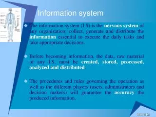
Introduction • Object-oriented (o-o) techniques work well in situations where complicated systems are undergoing continuous maintenance, adaptation, and design. • The Unified Modeling Language (UML) is an industry standard for modeling object-oriented systems.
Introduction The object-Oriented modeling approach provides several benefits, including: • Ability to tackle more challenging problem domains. • Improved communication among users, analysts, designers, and programmers.
Introduction The object-Oriented modeling approach provides several benefits, including: • Reusability of analysis, design, and programming results. • Maintaining systems • Increased consistency among the models developed during object-oriented analysis, design, and programming
Object- Oriented\Definitions and concepts Object: • An object, represents a real-world thing or event. • Objects may be customers, items, and so on. • Objects may be GUI displays or text areas on a display. • Objects are represented by and grouped into classes.
Object- Oriented\Definitions and concepts Object \ Example
Object- Oriented\Definitions and concepts Class: • A classis a group of related objects has a set of shared attributes and behaviors. • Attributes are properties of a class possessed by all objects. • A method (Operation) is an action that can be requested from any object in the class. • Instantiate is a term used when an object is created from a class. • Behavior is a manner that represents how an object acts and reacts
Object- Oriented\Definitions and concepts Class \ Example
Object- Oriented\Definitions and concepts Class:\ Example
Object- Oriented\Definitions and concepts Messages: Information sent by one object to another
Object- Oriented\Definitions and concepts Inheritance: • Inheritance is when a new class is created from another class. • The original class is the parent or base class. • The new class is the child or derived class. • The child class receives the attributes and methods of the parent class.
Object- Oriented\Definitions and concepts Inheritance \ Example
Object- Oriented\Definitions and concepts Encapsulation: • Encapsulation means objects can be accessed only through their interfaces. The caller has no knowledge of variables inside and how the method is implemented. As long as the interfaces are the same, changes to the internal details can be made without changing the code that uses the objects.
Object- Oriented\Definitions and concepts Encapsulation: • In object-oriented, the technique of hiding the internal implementation details of an object from its external view • The object is said to "publish its interfaces." Other objects adhere to these interfaces to use the object without having to be concerned with how the object accomplishes it. The idea is "don't tell me how you do it; just do it."
Object- Oriented\Definitions and concepts Encapsulation \ Example
Object- Oriented\Definitions and concepts Polymorphism: In object-oriented programming, polymorphism refers to a programming language's ability to process objects differently depending on their data type or class. More specifically, it is the ability to redefine methods for derived classes.For example, given a base class shape, polymorphism enables the programmer to define different area methods for any number of derived classes, such as circles, rectangles and triangles.
Object- Oriented\Definitions and concepts Polymorphism \ Example
Unified Modeling Language/ UML • The Unified Modeling Language (UML) is a graphical language for visualizing, specifying, constructing, and documenting the artifacts of a software systems.
Unified Modeling Language/ UML Visualizing: • Explicit model facilitates communication • Each symbol has well-defined semantics behind it
Unified Modeling Language/ UML Visual Modeling: • VISUAL MODELING is a way of thinking about problems using (graphical) models organized around real-world idea. • UML is a product of VISUAL MODELING language.
Unified Modeling Language/ UML Specifying: • UML addresses the specification of all important analysis, design, and implementation decisions.
Unified Modeling Language/ UML Constructing: • Forward engineering: generation of code from model into programming language • Reverse engineering: reconstructing model from implementation • Round-trip engineering: going both ways
Unified Modeling Language/ UML Documenting: • Deliverables, such as requirements documents, functional specifications, and test plans • Materials that are critical in controlling, measuring, and communicating about a system during development and after deployment
Unified Modeling Language/ UML Models are useful for: • understanding problems, • communicating with everyone involved with project (customer, analysts, designers, etc.) • preparing documentation • designing programs and databases
Unified Modeling Language/ UML What is a good Model? • it is a relevant model • it is possible to communicate • it fits its purpose • it captures the essentials
Unified Modeling Language/ UML What does UML give you? • The UML gives you a standard way to write a system’s blueprints covering conceptual things, such as business processes and system functions, classes written in a specific programming language, database schemas, and reusable software components.
Unified Modeling Language/ UML Note: • UML is phase independent and it is a modeling language (NOT a method)
Unified Modeling Language/ UML UML Diagrams: • Structural Type Diagrams (Static Representations) • Class Diagrams • Behavioral Type Diagrams (Dynamic Representations) • Activity Diagrams • Use Case Diagrams • Sequence Diagrams
Unified Modeling Language/ UML Activity Diagram: • The easiest way to visualize an Activity diagram is to think of a flowchart of a code. • Activity diagrams represent the business and operational workflows of a system • An Activity diagram is a dynamic diagram that shows the activity and the event that causes the object to be in the particular state.
Unified Modeling Language/ UML How to Draw Activity Diagram: • Activity diagrams show the flow of activities through the system • Diagrams are read from top to bottom and have branches and forks to describe conditions and parallel activities. • A fork is used when multiple activities are occurring at the same time. • The branch describes what activities will take place based on a set of conditions • All branches at some point are followed by a merge to indicate the end of the conditional behavior started by that branch. • After the merge all of the parallel activities must be combined by a join before transitioning into the final activity state
Unified Modeling Language/ UML Activity diagram \ Example 1: Manage course information
Unified Modeling Language/ UML Activity diagram \ Example 2 : Ordering
Unified Modeling Language/ UML Activity diagram \ Example 3 : Prepare Beverage
Unified Modeling Language/ UML Use Case Diagram: • UML Use Case Diagrams can be used to describe the functionality of a system. • Use case diagram is done in the early stages of system development (during the analysis phase) to help developers understand the functional requirements of the system without worrying about how those requirements will be implemented.
An Actor Unified Modeling Language/ UML Use Case Diagram have the following Elements: • Actor: • Is an external entity that interact with the system (similar to EE in DFD). • It is someone or something that exchanges information with the system. • An actor is a role that a user plays in the system • What is the Different between Actor & User?
Unified Modeling Language/ UML Use Case Diagram have the following Elements: • Actor: • A user of the system may play several different roles through the course of his, her or its job (since an actor may be another system). • Examples of actors are salesperson, manager, support person, and web store system. It is possible that the same person may be a sales person and also provide support.
Unified Modeling Language/ UML Use Case Diagram have the following Elements: • Use Case: • Represents a sequence of related actions initiated by an actors, it’s a specific way of using the system • A use case is a set of scenarios that describing an interaction between a user and a system. • A use case diagram displays the relationship among actors and use cases.
Unified Modeling Language/ UML Use Case: Example • Print Invoice • Correct Invoice • Chase Payment • Register Bad Debt
Unified Modeling Language/ UML Actors and Use Cases: • An Actor may use many Use Cases • A Use Case may interface with many Actors • We draw a simple line to indicate interaction
A Use Case An Actor Unified Modeling Language/ UML Relationships between actors and use cases: The direction of the arrow indicates who initiates the interaction.
A Use Case An Actor Unified Modeling Language/ UML Relationships between actors and use cases: Sometimes the use case initiates interaction
Unified Modeling Language/ UML • Relationship between Use cases: • One Use Case may use another Use Case • Sometimes a Use Case gets too big to manage sensibly and it makes sense to break this down into smaller Use Cases.
<<include>> Change Invoice Add item to sales menu Unified Modeling Language/ UML There are two ways Use Cases can relate: • Use Cases include other Use Cases \ <<uses>> In this case the second Use Case is always invoked as part of the execution of the first.
Unified Modeling Language/ UML There are two ways Use Cases can relate: • Use Cases extend other Use Cases <<extend>> Chase Payment Issue Warning Letter A Use Case is only called occasionally from another Use Case
Unified Modeling Language/ UML Use Case Diagram / Guidelines: • Use Case Names Begin With a Strong Verb • Name Use Cases Using Domain Terminology • Place Your Primary Use Cases In The Top-Left Corner Of The Diagram • Imply Timing Considerations By Stacking Use Cases.
Unified Modeling Language/ UML Use Case Diagram / Example 1:
Unified Modeling Language/ UML Example 2
Unified Modeling Language/ UML Example 3
Unified Modeling Language/ UML Example 3
Unified Modeling Language/ UML Example 4