Download
1 / 33
330 likes | 560 Vues
IP Routing, Format, Fragmentation. Chapters 20-21, 23. IP . IP is connectionless in the end-to-end delivery Data delivered in datagrams (packets / frames), each with a header Combines collection of physical networks into single, virtual network

E N D
IP Routing, Format, Fragmentation Chapters 20-21, 23
IP • IP is connectionless in the end-to-end delivery • Data delivered in datagrams (packets / frames), each with a header • Combines collection of physical networks into single, virtual network • Transport protocols use this connectionless service to provide connectionless data delivery (UDP) and connection-oriented data delivery (TCP) • But this is all done on top of IP, which is connectionless, so we’ll need to implement quite a bit of extra logic in TCP to get the connection-oriented characteristics out of an underlying connectionless medium
Virtual Packets • Packets serve same purpose in internet as frames on LAN • Routers (or gateways) forward packets between physical networks • Packets have a uniform, hardware-independent format • Includes header and data • Why are these “virtual?” Because we would like a packet to be capable of crossing multiple networks, where networks could use different types of technologies (e.g. Token Ring, Ethernet) • The virtual packet is implemented by encapsulating it in hardware frames for delivery across each physical network • Ensures universal format across heterogenous networks
The IP Datagram • Formally, the unit of IP data delivery is called a datagram • Includes header area and data area • Datagrams can have different sizes • Header area usually fixed (20 octets) but can have options • Data area can contain between 1 octet and 65,535 octets (216- 1) • Usually, data area much larger than header (why?)
Forwarding Datagrams • The header contains all the information needed to deliver a datagram to a destination computer • Destination address • Source address • Identifier • Other delivery information • Routers examine the header of each datagram and forwards the datagram along a path to the destination • Use routing table to compute next hop • Update routing tables using algorithms previously discussed • Link state, distance vector, manually
Routing Tables and Address Masks • In practice, destination stored as network address • Next hop stored as IP address of router • Address mask defines how many bits of address are in prefix • Prefix defines how much of address used to identify network • E.g., class A mask is 255.0.0.0 • Used for subnetting Routing Table for Center Router
Address Masks • To identify destination network, apply address mask to destination address and compare to network address in routing table • Can use Boolean AND • if ((Mask[i] & D) == Dest[i]) forward to NextHop[i] • Consider 128.1.15.26:
Forwarding IP Packets • Destination address in IP datagram is always ultimate destination • Router looks up next-hop address and forwards datagram • Network interface layer takes two parameters: • IP datagram • Next-hop address • Next-hop address never appears in IP datagram
IP is Best Effort Delivery • IP provides service equivalent to LAN • Does not guarantee to prevent • Duplicate datagrams • Delayed or out-of-order delivery • Corruption of data • Datagram loss • Reliable delivery provided by transport layer • Network layer - IP - can detect and report errors without actually fixing them
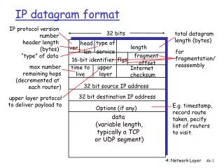
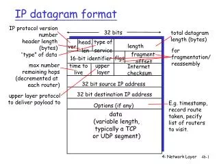
IPv4 Datagram Format IP protocol version number 32 bits total datagram length (bytes) header length (32 bits) type of service head. len ver Total length for fragmentation/ reassembly fragment offset “type” of data flgs 16-bit identifier max number remaining hops (decremented at each router) upper layer time to live Internet checksum 32 bit source IP address 32 bit destination IP address upper layer protocol to deliver payload to E.g. timestamp, record route taken, specify list of routers to visit. Options (if any), plus padding data (variable length, typically a TCP or UDP segment)
Parameters (1) • Source address • Destination address • Upper Layer Protocol • Recipient e.g. TCP • Type of Service • Specify treatment of data unit during transmission through networks • Ignored by many routers • Identifier • Uniquely identifies PDU for a particular sender/receiver • Needed for re-assembly and error reporting • “Send” only; i.e. in sending a data packet, not used for Deliver or “ACK” mode • Fragmentation dropped in IP6
Parameters (2) • Flags (3 bits) • First: Is this data fragmented? • Second: Are we allowed to fragment the data? • If not, may not be possible to deliver • Third: not used • Time to live • Prevent datagram from traveling forever by decrementing each hop • Header length • In groups of 4 bytes • Total length • In bytes, includes header and data • Option data • User data
Type of Service • Might be useful to differentiate traffic, e.g. ICMP vs. data, or real-time data vs. non-real time • Precedence • 8 levels • Reliability • Normal or high • Delay • Normal or low • Throughput • Normal or high • These are often ignored by routers
Options • Meant to be used rarely. Way to extend the IP protocol with a variable number of options. Dropped in IPv6. • Security • Source routing • Route recording • Stream identification • Timestamping • Since this is optional, it means headers can be of variable length • This is why we need the Header Length field • If an IP datagram has no options, H-LEN = 5 • Header with 96 bits of options has H-LEN = 8 • If options don’t end on a 32-bit boundary, padding (all zero’s) added to make this a multiple of 32 bits • See why H-LEN is in groups of 32 bits?
Datagram Lifetime • Datagrams could loop indefinitely • Consumes resources • Transport protocol may need upper bound on datagram life • Datagram marked with lifetime • Time To Live field in IP • Once lifetime expires, datagram discarded (not forwarded) • Hop count • Decrement time to live on passing through a each router • Time count • Need to know how long since last router
Data Field • Carries user data from next layer up • Likely UDP/TCP packet • Integer multiple of 8 bits long (octet) • Max length of datagram (header plus data) 65,535 octets
Datagram Transmission and Frames • IP internet layer • Constructs datagram • Determines next hop • Hands to network interface layer • Network interface layer • Binds next hop address to hardware address • Prepares datagram for transmission • But ... hardware frame doesn't understand IP; how is datagram transmitted?
Encapsulation • Network interface layer encapsulates IP datagram as data area in hardware frame • Hardware ignores IP datagram format • Standards for encapsulation describe details • Standard defines data type for IP datagram, as well as others (e.g., ARP) • Receiving protocol stack interprets data area based on frame type
Encapsulation Across Multiple Hops • Each router in the path from the source to the destination: • Unencapsulates incoming datagram from frame • Processes datagram - determines next hop • Encapsulates datagram in outgoing frame • Datagram may be encapsulated in different hardware format at each hop • Datagram itself is (almost!) unchanged Ethernet Token Ring Wireless
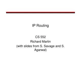
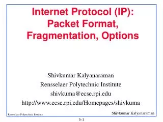
Network links have MTU (max.transfer size) - largest possible link-level frame. different link types, different MTUs large IP datagram divided (“fragmented”) within net one datagram becomes several datagrams “reassembled” only at final destination IP header bits used to identify, order related fragments IP Fragmentation & Reassembly fragmentation: in: one large datagram out: 3 smaller datagrams reassembly
Fragmentation and Re-assembly • Different packet sizes • When to re-assemble • At destination only • Results in packets getting smaller as data traverses internet • Why not re-assemble at intermediate routers? • Need large buffers at routers • Buffers may fill with fragments • All fragments must go through same router • Inhibits dynamic routing • Routers have enough work to do already without having to reassemble stuff
IP Fragmentation • IP re-assembles at destination only • Uses fields in header • Data Unit Identifier (ID) • Identifies end system originated datagram if coupled with: • Source and destination address • Protocol layer generating data (e.g. TCP) • Identification supplied by that layer • Data length • Length of user data in octets • Offset • Position of fragment of user data in original datagram • In multiples of 64 bits (8 octets) • More flag • Indicates that this is not the last fragment
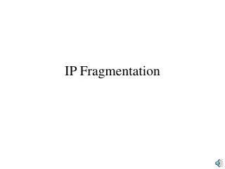
IP Fragmentation and Reassembly length =1500 length =1040 length =4000 length =1500 ID =x ID =x ID =x ID =x moreflag =1 moreflag =1 moreflag =0 moreflag =0 offset =2960 offset =0 offset =0 offset =1480 One large datagram becomes several smaller datagrams
Fragmenting Fragments • A fragment may encounter a subsequent network with even smaller MTU • Router fragments the fragment to fit • Resulting (sub)fragments look just like original fragments (except for size) • No need to reassemble hierarchically; (sub)fragments include position in original datagram
Dealing with Failure • Re-assembly may fail if some fragments get lost • Need to detect failure • Re-assembly time out • Assigned to first fragment to arrive • If timeout expires before all fragments arrive, discard partial data
Error Control • Not guaranteed delivery • Router should attempt to inform source if packet discarded • e.g. for time to live expiring • Source may modify transmission strategy • May inform high layer protocol • Datagram identification needed • Destination doesn’t ACK or NAK if checksum fails, no retries, best-effort like Ethernet
Flow Control • Allows routers and/or stations to limit rate of incoming data • Limited in connectionless systems • Send flow control packets • Requesting reduced flow • e.g. ICMP
ICMP • Internet Control Message Protocol • RFC 792 • Transfer of (control) messages from routers and hosts to hosts • Feedback about problems • e.g. time to live expired, destination unreachable (e.g. no ARP reply), checksum fails (header only!), no route to destination, etc. • Considered “part” of IP, but it is really a user of IP • Encapsulated in IP datagram • Not reliable • ICMP messages sent in response to incoming datagrams with problems • ICMP message not sent for ICMP message
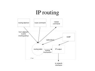
Used by hosts, routers, gateways to communication network-level information error reporting: unreachable host, network, port, protocol echo request/reply (used by ping) ICMP message: type, code plus first 8 bytes of IP datagram causing error ICMP: Internet Control Message Protocol TypeCodedescription 0 0 echo reply (ping) 3 0 dest. network unreachable 3 1 dest host unreachable 3 2 dest protocol unreachable 3 3 dest port unreachable 3 6 dest network unknown 3 7 dest host unknown 4 0 source quench (congestion control - not used) 8 0 echo request (ping) 9 0 route advertisement 10 0 router discovery 11 0 TTL expired 12 0 bad IP header
ICMP and Ping • An internet host, A, is reachable from another host, B, if datagrams can be delivered from A to B • ping program tests reachability - sends datagram from B to A that A echoes back to B • Uses ICMP echo request and echo reply messages • Internet layer includes code to reply to incoming ICMP echo request messages
ICMP and Traceroute • List of all routers on path from A to B is called the route from A to B • traceroute uses UDP to non-existent port and TTL field to find route via expanding ring search • Sends ICMP echo messages with increasing TTL • Router that decrements TTL to 0 sends ICMP time exceeded message, with router's address as source address • First, with TTL 1, gets to first router, which discards and sends time exceeded message • Next, with TTL 1, gets through first router to second router • Continue until message from destination received • traceroute must accommodate varying network delays • Must also accommodate dynamically changing routes
ICMP and MTU Discovery • Fragmentation should be avoided for optimal performance • How can source configure outgoing datagrams to avoid fragmentation? • Source determines path MTU - smallest network MTU on path from source to destination • Source probes path using IP datagrams with don't fragment flag • Router responds with ICMP fragmentation required message • Source sends smaller probes until destination reached
ICMP and Redirect • Default route may cause extra hop • Host A is sending a packet to Host B. Host A's default IP router is router R1. Host A forwards the packet destined for Host B to its default router R1. • R1 checks its routing table and finds that the next hop for the route to the network for Host B is router R2. • If Host A and R2 are on the same network that is also directly attached to R1, an ICMP Redirect message is sent to Host A informing it that R2 is the better route when sending to Host B. • Router R1 then forwards the IP datagram to R2. • Host A adds a host route to its routing table for Host B's IP address with router R2's IP address as the forwarding address. Subsequent datagrams from Host A to Host B are forwarded by means of router R2.