Effects of Imaging Parameters
90 likes | 242 Vues
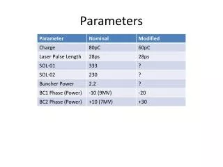
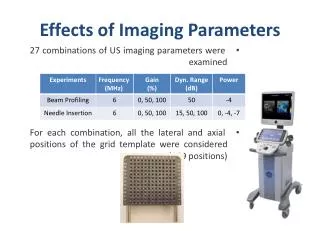
Effects of Imaging Parameters. 27 combinations of US imaging parameters were examined For each combination, all the lateral and axial positions of the grid template were considered (169 positions). Beam Profile Vs. Needle Tip Profile. Beam Profile Vs. Needle Tip Profile. Contributions.

Effects of Imaging Parameters
E N D
Presentation Transcript
Effects of Imaging Parameters • 27 combinations of US imaging parameters were examined • For each combination, all the lateral and axial positions of the grid template were considered (169 positions)
Contributions • Designed a beam profiling phantom compatible with commercial steppers • Generated beam profiles for all axial and lateral positions • Measured needle tip localization error over all lateral and axial positions • Examined the effects of US imaging parameters on needle tip localization error • Identified the best region within the US image slices with highest accuracy in object localizations
Future Works • Measure the beamwdiths of a linear and curvilinear transducers • Examine the needle tip error by targeting needles in animal tissues • Automate the beamwidth segmentation process • Eliminate artifacts by changing the beam forming algorithm • Incorporate the US beam profiles and localization errors into important surgical navigation systems
References • [1] A. Jemal, R. Siegel, J. Xu, and E. Ward, “Cancer Statistics.,” Ca-Cancer Journal for Clinicians. Vol. 60, pp 260-277, April (2010). • [2] S. Nag, D. Beyer, J. Friedland, P. Grimm, and R. Nath, “American brachytherapy society recommendations for transperineal permanent brachytherapy of theprostate cancer” Int. J. of Radiation Oncology, Biol., Phys. Vol. 44, pp 789-799, (1999). • [3] P. Bownes, and A. Flynn, “Prostate brachytherapy: a review of current practice”, J. Radiotherapy in Practice, Vol. 4, pp 86-101, (2004). • [4] W. R. Hedrick, D. L. Hykes, and D. E. Starchman, Ultrasound Physics and Instrumentation, Elsevier, Mosby, Missouri (2004). • [5] W. R. Hendee, and E. R. Ritenour, Medical Imaging Physics, John Willeys and Sons Inc.,New York, USA (2002). • [6] P. Hoskins, K. Martin, and A. Thrush, Diagnostic Ultrasound, Physics and Equipment, Cambridge University Press, Cambridge, UK (2010). • [7] A. Thrush, and T. Hartshrone, Peripheral Vascular Ultrasound, Elsevier, Philadelphia, USA (2005).
References • [8] A. Goldstein, and B. L. Madrazo, “Slice Thickness Artifacts in Gray-Scale Ultrasound.,” Journal of Clinical Ultrasound. Vol. 9, pp 365-375, Sep (1981). • [9] ML. Skolnick, “Estimation of Beam Width in the Elevation (Section Thickness) Plane.,” Radiology. Vol. 108, pp 286-288, (1991) • [10] B. Richard, “Test Object for Measurement of Section Thickness at Ultrasound.,” Radiology. Vol. 221, pp 279-282, (1999) • [11] T. K. Chen, A. D. Thurston, M. H. Moghari, R. E. Ellis, and P. Abolmaesumi, “A Real-Time Ultrasound Calibration System with Automatic Accuracy Control and Incorporation of Ultrasound Section Thickness.,” SPIE Medical Imaging. (2008) • [12] M. Peikari, T. K. Chen, C. Burdette, and G. Fichtinger, “Section-Thickness Profiling for Brachytherapy Ultrasound Guidance.,” SPIE Medical Imaging. (2011) • [13] F. C. Liang, and A. B. Kurtz, “The Importance of Ultrasonic Side-Lobe Artifacts.,” Radiology. Vol. 145, pp 763-768,Dec (1982) • [14] K. A. Scanlan, “Sonographic Artifacts and Their Origins.,” American Journal of Roentgenology. Vol. 156, pp 1267-1272, (1991) • [15] P. Y. Barthez, R. Leveille and P. V. Scrivani, “Side Lobes and Grating Lobes Artifacts in Ultrasound Imaging.,” Radiology and Ultrasound. Vol. 38, pp 387- 393, (1997) • [16] M. K. Feldman, S. Katyal and M. S. Blackwood, “US Artifacts.,” RadioGraphics. Vol. 29, pp 1179-1189, (2009)
References • [17] J. F. Synnevag, A. Austeng and S. Holm, “Adoptive Beamforming Aplied to Medical Ultrasound Imaging.,” IEEE. Vol. 54,No. 8, August (2007) • [18] J. F. Synnevag, and A. Austeng, “Minimum variance adaptive beamforming applied to medical ultrasound imaging.,” in Proc. IEEE Ultrason. Symp., 2005, pp. 1199.1202. • [19] B. Mohammadzadeh Asl, and A. Mahloojifar, “Eigenspace-Based Minimum Variance Beamforming Applied to Medical Ultrasound Imaging.,” IEEE. Vol. 57, No. 11, November (2010) • [20] J. A. Mann, and W. F. Walker, “A constrained adaptive beamformer for medical ultrasound: Initial results.,” in Proc. IEEE Ultrason. Symp., 2002, pp. 18071810 • [21] Z. Wang, J. Li, and R. Wu, “Time-delay- and timereversal-based robust Capon beamformers for ultrasound imaging.,” IEEE Trans. Med. Imag., vol. 24, pp. 13081322, Oct. 2005. • [22] J. Bax, D. Smith, L. Bartha, J. Montreuil, S. Sherebrin, L. Gardi, C. Edirisinghe, and A. Fenster, “A compact mechatronic system for 3D ultrasound guided prostate interventions.,” Physics in Medicine, vol. 38, pp. 1055-1069, Feb. 2011.