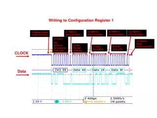
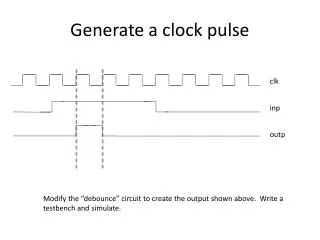
Generate a clock pulse
Generate a clock pulse. clk. inp. outp. Modify the “debounce” circuit to create the output shown above. Write a testbench and simulate. 4-bit Shift register. q3. q2. q1. q0. Data_in. clk. D Q clk reset. D Q clk reset. D Q clk reset. D Q

Generate a clock pulse
E N D
Presentation Transcript
Generate a clock pulse clk inp outp Modify the “debounce” circuit to create the output shown above. Write a testbench and simulate.
4-bit Shift register q3 q2 q1 q0 Data_in clk D Q clk reset D Q clk reset D Q clk reset D Q clk reset reset Serial data in the form of a string of bits is fed into the left-most flip-flop via data_in. At each clock pulse whatever is at data_in is moved to q3, the old value at q3 goes to q2, the old value at q2 got to q1 and the old value at q1 goes to q0. Note that all data values are shifted simultaneously on the same rising edge of the clock. Code this circuit and write a testbench to simulate.
More Problems Design a 2-bit “funny” counter using two DFF’s with outputs q1 and q0 where q1 is the most-significant bit. This counter will count in the following order: 2, 1, 3, 0, and then repeat. Derive the logic equations for d1 and d0 ( the inputs to the DFF’s ) Draw a logic diagram for this 2-bit counter Write the Verilog code and testbench Simulate Write a Verilog program and testbench for an 8-bit shift register. Simulate. Write a Verilog program and testbench for 3-bit down counter that counts down from 7 to 0 and then wraps back to 7. Simulate.
Johnson Counter q3 q2 q1 q0 Data_in D Q clk reset D Q clk reset D Q clk reset D Q clk ~Q reset clk reset Assume that q [3:0] = 0000 at the start. Make a table to show what the outputs q [3:0] will be after each clock pulse for the next 8 clock pulses.