Download
1 / 39
400 likes | 597 Vues
LES Simulation of Transient Fluid Flow and Heat Transfer in Continuous Casting Mold. Bin Zhao Department of Mechanical Engineering University of Illinois at Urbana-Champaign 10/ 2002. Acknowledgements. Professor B.G.Thomas & Professor S.P. Vanka Accumold AK Steel

E N D
LES Simulation of Transient Fluid Flow and Heat Transfer in Continuous Casting Mold Bin Zhao Department of Mechanical Engineering University of Illinois at Urbana-Champaign 10/ 2002
Acknowledgements • Professor B.G.Thomas & Professor S.P. Vanka • Accumold • AK Steel • Columbus Stainless Steel • Hatch Associates • National Science Foundation • National Center for Supercomputing Applications
Previous Work • LES flow and heat transfer simulations of an unconstrained impinging cylindrical jet. • LES flow simulations had insufficient grid refinement near walls for heat transfer. • High grid density needed near the impingement plate in order to get correct prediction of heat transfer rate without wall models.
Objectives • Study transient fluid flow in continuous casting mold region: (eg. AK Steel thin slab mold). • Study turbulent heat transfer in the casting mold liquid pool.
Simulation of Fluid Flow and Heat Transfer in the AK Steel Thin Slab Mold ¼ mold simulation
Computational details • Solving 3D transient Navior-Stokes Equations • Second Order accuracy in space and time • Non-Structured Cartesian collocation grid • Algebraic Multi-Grid (AMG) solver is used to solve pressure Poisson Equation • No sub-grid model (Coarse Grid DNS) • 3D flux-limited advection scheme • 852,442 finite volume cells • Time step 0.0005s
Simulation parameters * Nozzle geometry based on blueprints
Mesh for the nozzle part A-A D-D A A B B B-B E-E C C C-C *note: mesh of half of the mold, ¼ actually used in the simulation. D D E E
Mesh for the mold part A-A A A B-B B B *note: mesh of half of the mold, ¼ actually used in the simulation.
Instantaneous velocity vs. dye injection experiment Instantaneous velocity field at 50s Dye injection experiment by R. O’Malley (Armco, Inc)
Time-averaged velocity vs. dye-injection experiment Velocity field averaged from 30s to 50s Dye injection experiment by R. O’Malley (Armco, Inc)
Profile Location 50 mm NF SEN Measurement Position Temperature comparison (I)
Profile Location 125 mm NF SEN Measurement Position Temperature comparison (II)
Profile Location Middle Point NF SEN Measurement Position Temperature comparison (III)
Profile Location 125 mm NF SEN Measurement Position Temperature comparison (IV)
Profile Location 50 mm NF SEN Measurement Position Temperature comparison (V) Probe broken
Observations • NF heat flux may be a little lower than reality . • Heat flux peak at NF impingement is 800 kw/m2, instantaneously reaches 1,300 kw/m2; peak at small jet impingement point on WF is 500 kw/m2 , instantaneously reaches 700 kw/m2 . • No upper roll in the flow field. • Temperature in the upper corner region is too low. • Jed diffuse a lot in the vertical direction, resulting in weak impingement and low NF heat flux.
Simulation of Fluid Flow and Heat Transfer in the AK Steel Thin Slab Mold ½ mold simulation
Computational details • Mesh: doubled (reflected) ¼ mold domain & mesh. • 1,651,710 finite volume cells. • Use the result of ¼ mold simulation as initial condition. • Other parameters and conditions are identical to the ¼ mold simulation.
Instantaneous velocity field v.s. dye injection experiment Instantaneous velocity field at 9s Dye injection experiment by R. O’Malley (Armco, Inc)
Profile Location 50 mm NF SEN Measurement Position Temperature comparison (I)
Profile Location 125 mm NF SEN Measurement Position Temperature comparison (II)
Profile Location Middle Point NF SEN Measurement Position Temperature comparison (III)
Profile Location 125 mm NF SEN Measurement Position Temperature comparison (IV)
Profile Location 50 mm NF SEN Measurement Position Temperature comparison (V) Probe broken
Observations • The flow field now shows tendency towards an upper roll. • The jet has less diffusion in the vertical direction compared to the ¼ mold simulation: ie. has more penetration power. • Applying WF-WF symmetry (cutting through a jet) is inappropriate for transient simulations.
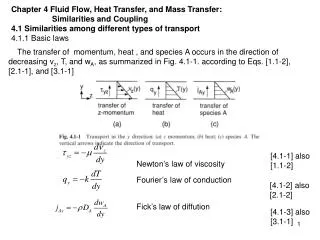
Future Work • Continue the ½ mold simulation. • Add shell shape into the simulation. • Investigate thermal buoyancy