Download
1 / 29
290 likes | 316 Vues
Learn about J-PARC's accelerators, operation modes, beam power history, and upgrade strategies for increased efficiency. Presented at a workshop, this comprehensive overview covers key components and advancements in beam technology.

E N D
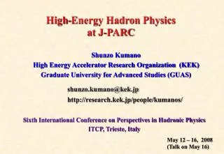
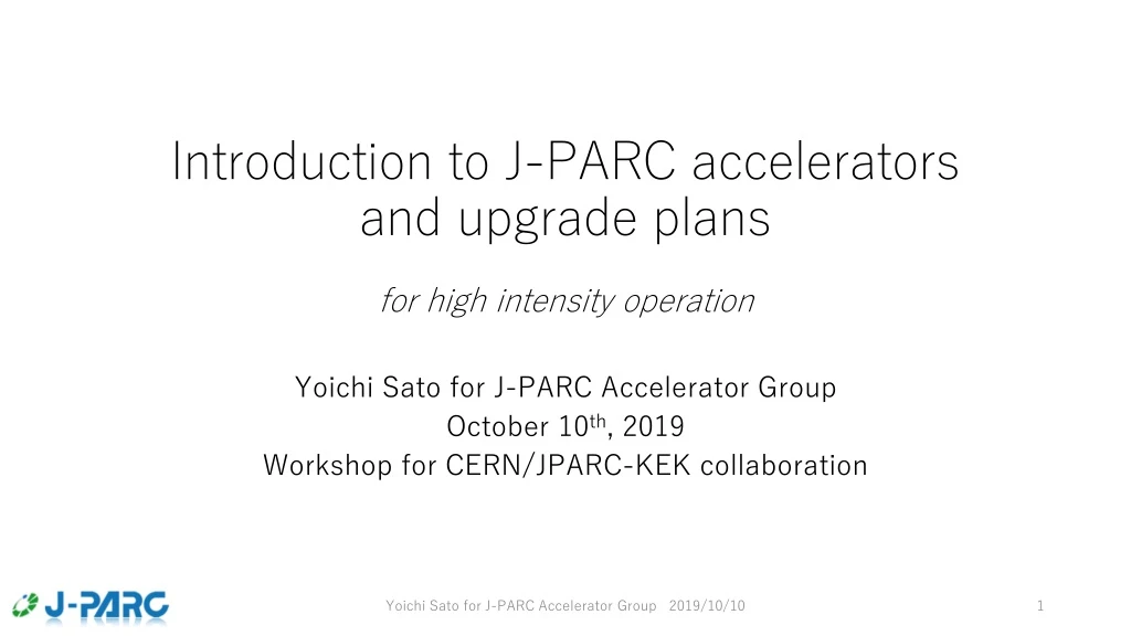
Introduction to J-PARC accelerators and upgrade plans for high intensity operation Yoichi Sato for J-PARC Accelerator Group October 10th, 2019 Workshop for CERN/JPARC-KEK collaboration Yoichi Sato for J-PARC Accelerator Group 2019/10/10
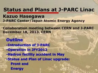
Contents • Overview • MR with fast extraction • High intensity tuning keys • Typical operation • MR upgrade plan • Concept and Preparation • Summary • Some topics are discussed in detail at this meeting: • Beam monitor upgrade plan, KenichiroSatou • J-PARC RF upgrade plan. Masahito Yoshii • J-PARC MR beam dump, Masashi Shirakata Yoichi Sato for J-PARC Accelerator Group 2019/10/10
N S E W 400-MeV H- Linac Japan Proton Accelerator Research Complex(J-PARC) 3-GeV Rapid Cycling Synchrotron (RCS) Neutrino Experimental Facility Fast extraction mode Materials & Life Science Experimental Facility (MLF) (3 GeV) 30-GeV Main Ring (MR) Synchrotron Slow extraction mode Hadron Experimental Facility Yoichi Sato for J-PARC Accelerator Group 2019/10/10
Power History RCS to MLF; Stable 1 MW demonstration 1 MW demonstration (10.5 hours on 2019/7/3) H. Hotchi, et. al. 1 hour 10.5 hour Well controlled beam losses. Very stable during the 10.5 hours. Only 3 MPSs at Linac & no MPS at RCS. MPS threshold 1 MW demo. BLM integrated signal (arb.) BLM IDs 1.2 MW eq. Beam Intensity Linac 57 mA MLF user op. 540 kW MLF beam power has steadily increased The beam power of the recent user operation is 540 kW. The power will be increased by carefully confirming the soundness of the neutron production target. The operation of the original beam power target of 1 MW was successfully demonstrated. High power beam operation beyond 1 MW is planned. Accelerating 1.2 MW eq. up to 1 GeV was demonstrated. Yoichi Sato for J-PARC Accelerator Group 2019/10/10
Main parameters of MR Circumference 1567.5 m Injection energy 3 GeV Extraction energy 30 GeV Super-periodicity 3 harmonic 9 Number of bunches 8 Rf frequency 1.67 - 1.72 MHz Transition j 31.7 (typical) Physical Aperture 3-50 BT Collimator 54-65 p.mm.mrad 3-50 BT physical ap. > 120 p.mm.mrad Ring Collimator 54-70 p.mm.mrad Ring physical ap. > TWO OPERATION MODES: • Fast extraction mode (FX) for the neutrino experiment: 1 turn extraction • Slow extraction mode (SX) for the hadron hall experiments: 2 s extraction FX beam power 0.75 MW (design) 0.50 MW (present) SX Cycle time 5.20 s FX Cycle time 2.48 s Beam power [W] = Ave. Beam Current [A=C/s] ×Beam Energy [eV] = Number of charged particles [C/pulse]×Number of pulse [pulse/s] ×Beam Energy [eV] HIGHER repetition MORE particles Yoichi Sato for J-PARC Accelerator Group 2019/10/10
Beam Power History MR to NU/HD Max. delivered power: Fast extraction ~500 kW in 2.48 s cycle (2.6E14 ppp) Slow extraction ~51 kW in 5.20 s cycle (5.5E13 ppp) NU w FX (21.35, 21.43) Accident at Hadron Facility Earthquake HD w SX (22.40, 20.75) DATE As of May 2019 • Stable NU 490 kW user operation with 500 W loss • NU 500 kW operation (50 series shots) successfully with 700 W loss Tune diagrams of MR. Solid lines: structure up to 3rd resonances Dashed: non-structure half-integer & linear coupling resonances Yoichi Sato for J-PARC Accelerator Group 2019/10/10
Beam Power History MR to NU/HD Max. delivered power: Fast extraction ~500 kW in 2.48 s cycle (2.6E14 ppp) Slow extraction ~51 kW in 5.20 s cycle (5.5E13 ppp) NU w FX (21.35, 21.43) Accident at Hadron Facility Earthquake HD w SX (22.40, 20.75) DATE As of May 2019 • Stable NU 490 kW user operation with 500 W loss • NU 500 kW operation (50 series shots) successfully with 700 W loss Tune diagrams of MR. Solid lines: structure up to 3rd resonances Dashed: non-structure half-integer & linear coupling resonances Yoichi Sato for J-PARC Accelerator Group 2019/10/10
Tuning items S. Igarashi, HB2018 Y. Sato, IPAC2018 MR Power 500 kW Space Charge Tune Shift: 0.4 • Estimated from the measured transverse emittances and bunching factor • RCS parameters optimization for the injection beam • Optics measurements and corrections • with trim coils of main Q magnets for the leakage-fields of the FX septum magnets. Better symmetricity suppresses the effects of all resonance lines. • Operation betatron tune optimization • Tune tracking is adopted, also • Third order and higher order resonance corrections • with trim coils of four sextupole magnets. • with octupole magnets • Space charge mitigation with 2nd harmonic RF • Suppress the space charge tune shift • Transverse instability suppression • with chromaticity parameters and • Intra-bunch feedback system. • Collimator balancing • Beam halo cutting between 3-50BT and MR • To localize beam losses at collimator area 2νy = 43 νx + 2νy= 64 νy (21.35,21.43) 3νx = 64 2νx = 43 νx= 21 νx νx - νy= 0 νx - 2νy = -21 Operational betatron tune avoids - Structure resonances up to 3rd order - Non-structure resonances of half integer and linear coupling resonances Moreover, non-structure of higher order resonances are to be corrected. νy = 21 Yoichi Sato for J-PARC Accelerator Group 2019/10/10
Tuning items S. Igarashi, HB2018 Y. Sato, IPAC2018 MR Power 500 kW Space Charge Tune Shift: 0.4 • Estimated from the measured transverse emittances and bunching factor • RCS parameters optimization for the injection beam • Optics measurements and corrections • with trim coils of main Q magnets for the leakage-fields of the FX septum magnets. Better symmetricity suppresses the effects of all resonance lines. • Operation betatron tune optimization • Tune tracking is adopted, also • Third order and higher order resonance corrections • with trim coils of four sextupole magnets. • with octupole magnets • Space charge mitigation with 2nd harmonic RF • Suppress the space charge tune shift • Transverse instability suppression • with chromaticity parameters and • Intra-bunch feedback system. • Collimator balancing • Beam halo cutting between 3-50BT and MR • To localize beam losses at collimator area 2νy = 43 νx + 2νy= 64 νy (21.35,21.43) 3νx = 64 2νx = 43 νx= 21 νx νx - νy= 0 νx - 2νy = -21 All tuning items are relating each other. Iterative tunings are required at every power step. νy = 21 Yoichi Sato for J-PARC Accelerator Group 2019/10/10
S. Igarashi, HB2018 Y. Sato, IPAC2018 Typical operation of MR 490 kW to NU MR power 490 kW (2.5 e14 ppp) (4 batches = 8 bunches) w MR loss 480 W MR Loss Distribution MR Loss Location 2.48 sec cycle Acceleration Magnet excite pattern Extraction In non-COL area Monitor sensitivity×8 2 bunches at each injection Injection Time (s) • Tuning Items: • RCS conditions • Operationpoint • Optics corr. • Resonance line corr. • Instability damping • Space charge effect mitigation • Collimator balancing Acceleration Recovery Injection COL Non-COL (BLM w high gain) 0.01 + 0.13 s 0.94 s 1.4 s MR power 490 kW in 2.48 s cycle 3-50BT loss 50 W < BT COL capacity 2 kW MR loss 480 W < MR COL capacity 2 kW • MR total loss, ~ 1%, is well localized in COL section and low energy, and less than the COL capacity • Maintenance capability has been kept. All tuning items are relating each other. Iterative tunings are required at every power step. Yoichi Sato for J-PARC Accelerator Group 2019/10/10
High intensity trial at 520 kW Losses at the beginning of the acceleration: ArcB loss (@ high by) V-profile was large @ NU. Optimization necessary for loss reduction. Longitudinal oscillation enlarged but no leakage from RF bucket RF#3 anode current 100 A Y. Sato, IPAC2018 MR power 520 kW (2.68 e14 ppp) (4 batches = 8 bunches) w MR loss 1 kW MR Loss Distribution MR Loss Location 2.48 sec cycle Acceleration Magnet excite pattern Extraction In non-COL area Monitor sensitivity×8 2 bunches at each injection Injection Time (s) Acceleration Recovery Injection COL Non-COL (BLM w high gain) 0.01 + 0.13 s 0.94 s 1.4 s MR power 490 kW 500 kW 520 kW in 2.48 s cycle 3-50BT loss 50 W200 W < BT COL capacity 2 kW MR loss 480 W 700 W 1 kWunoptimized< MR COL capacity 2 kW • MR total loss, ~ 2%, is less than the COL capacity. 1.1 MW capability in 1.16 s near-future-cycle • The tuning items were optimized for 480 kW. After iterative tunings, we expect less losses. • Some improvements on longitudinal control are planned for stable operation of > 2.6 e14 ppp.
Contents • Overview • MR with fast extraction • High intensity tuning keys • Typical operation • MR upgrade plan • Concept and Preparation • Summary Yoichi Sato for J-PARC Accelerator Group 2019/10/10
Beam Power Upgrade Concept • The operation of 500 kW has been achieved so far with the cycle time of 2.48 s and the accelerated protons of 2.6 e14 ppp. • The beam power of 1.3 MW is planned with the faster cycling of 1.16 s and the accelerated protons of 3.3e14 ppp. More Protons Faster Cycle Hardwares (Magnet PS/ RF/ Colli/ Inj&FX/…) are to be ready by JFY2025. Aiming 1.3 MW by JFY2028. ・T. Koseki, IPAC2018, “Upgrade Plan of J-PARC MR” ・Accelerator Tech Design Report for MR 1.3 MW (1st Draft), https://kds.kek.jp/indico/event/30493/session/0/material/2/0.pdf Yoichi Sato for J-PARC Accelerator Group 2019/10/10
Mid-term Plan of MR FX: Faster cycling: 2.48 s ➝ 1.32 s for 750 kW ➝ 1.16 s for 1.3 MW SX: Mitigation of the residual radiation for 100 kW New buildings Mass production/installation/test Manufacture, installation/test Kicker PS improvement, Septa manufacture /test Kicker PS improvement, FX septa manufacture /test Local shields Yoichi Sato for J-PARC Accelerator Group 2019/10/10
New power supply for high repetition rate operation IPAC2019 T. Shimogawa 連続 The budget approved by the Government. - Three new building for the PS - Started mass production of the PS’s. Test results using a real magnet family Successful demonstration in 1.32 s cycle. 1.32 s New building and containers for capacitor banks Present BM-PS Tue current deviation at flat top. The new BM-PS reduced it by a factor 10 in the low freq. corresponding the magnetic field that a beam feels New BM-PS Capacitor bank New power supply for BM3 Yoichi Sato for J-PARC Accelerator Group 2019/10/10
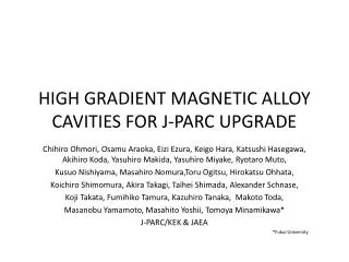
Higher rf voltage • Details are discussed: • J-PARC RF upgrade plan. Masahito Yoshii Higher rf voltages are necessary for the faster cycle operation. For this purpose, a magnetic alloy (MA) core, FT3L, is developed to increase shunt impedance of the rf cavity in a close collaboration between J-PARC and Hitachi Metal Co. Ltd. The coreis processed by annealing with magnetic field. Comparison of field gradient of rf cavities for proton synchrotron. Upgrade plan of rf system MA: FT3L MA: FT3M Ferrite All of the FT3M cavities in the MR have been replaced with the FT-3L cavities by 2016. Yoichi Sato for J-PARC Accelerator Group 2019/10/10
MR Collimator Upgrades (higher capacitor & better localization) M. Shirakata and Y. Sato, PASJ2017 Present from JFY 2021 • Upgrade MR collimator in JFY 2021: total capacity 2.0 3.5 kW • In the faster cycle, beam loss will increase linearly, and should be more localized • For further localization, • adding new collimators having angle adjusted jaws • 2 stage collimator scenario, using a scatterer, is under studied • Successful beam test: Less loss leakage without increasing total beam loss Yoichi Sato for J-PARC Accelerator Group 2019/10/10
MR Collimator: angle adjustment M. Shirakata and Y. Sato, PASJ2017 • Collimators C and H have angle adjustment capability • Fitting the collimator jaws to beam envelopes reduced loss leakage in non-collimator section • Additional rotational collimators (Col. D,F,G) are to be installed. Original Difference MR # address Non-collimator section BLM signal integrated in time Collimator section Less leakage from collimator section though less total loss at collimator Angles optimized Collimator section MR # address Yoichi Sato for J-PARC Accelerator Group 2019/8/28
MR Collimator: two-stage trial Beam test of two stage (450 kW eq.) Scatter Y. Sato, et, al, PASJ2017 • 2 stage collimator scenario, using thin-plates as scatterer, is under studied, besides adding new collimators having angle adjusted jaws. • Successful beam test: Less loss leakage without increasing total beam loss • Bent-crystal may be a good choice as the material of thin-plates • Note: MR-scatterer should be located at high radioactive area. Yoichi Sato for J-PARC Accelerator Group 2019/8/28
Injection and FX systems ・Injection Kicker needs upgrade for the matching box. ・Injection Septum Magnet and PS were replaced. ready for 1.16 s cycle. ・FX Kicker HV charger was upgraded. ready for 1.16 s cycle. ・FX Septum Magnets: Testing. Installation in 2021. Low Field Septum Magnets and PS constructed. High Field Septum Magnets constructed. New FX-SM30 (low field sept. mag.) test
Searching better operation tune to accelerate 30% more protons • Beam loss should be reduced for the beam intensity increase of ~30%. • Dynamic aperture at the current operation tune of (21.35, 21.45) is affected by the structure resonance of νx−2νy = −21. • Working points of (22.35, 22.45) and (21.35, 20.45) may be free from the structure resonances. • Beam study is necessary for the new working points. New possible w. p. (22.35, 22.45) Dynamic aperture survey (No magnetic error/ no space charge) S. Igarashi IPAC2019 Current w. p. (21.35, 21.45) 2νx−2νy=0 Previous w. p. (22.40, 20.75) New possible w. p. (21.35, 20.45) νx−2νy=−21 Yoichi Sato for J-PARC Accelerator Group 2019/10/10
Muli-MW Beams to the Neutrino Experiment (J-PARC) Conceptional Design of 8 GeV Ring Circumference 696.666 m Super-periodicity 4 Transition gamma ~15 GeV • Higher injection energy • Reduce space charge effect • Increase physical aperture • Reduce bunch length Adding new 8-GeV Booster in J-PARC enables 3.2 MW or more (~5 MW) Y.Sato S. Igarashi, et. al., J-PARC Symposium July 15, 2014 H. Hotchi et al, “Introducing an 8-GeV Booster Synchrotron between RCS and MR at J-PARC — One Possible Option toward a Multi-MW Output Beam Power from MR”, JPS Conf. Proc. 8, 012008 (2015) Yoichi Sato for J-PARC Accelerator Group 2019/10/10
What can we collaborate in the MR 1.3 MW upgrade plan? • In this meeting we are going to discuss • Beam monitor upgrade plan, KenichiroSatou • To observe more protons in faster cycle • To make finer beam tunings w better current deviation of Mag-PS • J-PARC RF upgrade plan. Masahito Yoshii • Higher rf voltage, heavier beam loadings • J-PARC MR beam dump, Masashi Shirakata • Present dump capacity is 7.5 kW 13 shots/hours for 3.3e14 ppp. • > 20 kW dump for smooth beam commissioning • Time schedule is under discussion • Others in discussion time • COD real-time correction, 2-stage collimation, Collimator real-time tunings, … Yoichi Sato for J-PARC Accelerator Group 2019/10/10
Summary • MR with fast extraction achieved stable 490~500 kW operation in 2.48 s cycle without significant beam loss. • MR upgrade is planned with preparing faster cycle (from 2.48 s to 1.16 s) to achieve 1.3 MW. 80% of required protons were accelerated in 2.48 s cycle (520 kW demonstration). • Hardwares are to be ready by JFY2025, and they are on schedule. The most powerful neutrino beam can be realized by JFY 2028. • We expect that our collaboration will help to realize the 1.3 MW scenario firmly. Yoichi Sato for J-PARC Accelerator Group 2019/10/10
Backups Yoichi Sato for J-PARC Accelerator Group 2019/10/10
H. Hotchi, IPAC2019 M. Yamamoto, IPAC2019 F. Tamura, IPAC2019 RCS: High Power Operation beyond 1 MW • The upgrade is planned for 1.5 MW with the 2nd target station of MLF. • The operation of 1.2 MW equiv. was demonstrated for the acceleration of up to 1 GeV. • RF system will be upgraded this summer for the beam loading compensation for the beam power beyond 1 MW. Beam Intensity 1.2 MW equiv. Yoichi Sato for J-PARC Accelerator Group 2019/10/10
Longitudinal Oscillation and RF Anode Currents for > 2.6e14 ppp operation Acceleration • The damper for the longitudinal oscillation is under preparation. • The application is essential for the 500 kW operation. • The current limit of the anode power supplies is an issue. • In JFY 2018 shutdown, optimized frequency response for beam energy (especially for low synchrotron oscillation) Injection Current Limit 10% Margin RF Anode Current (A) Fundamental Spare 2nd harmonic Yoichi Sato for J-PARC Accelerator Group 2019/10/10 Acceleration Injection
Necessity of upgrading the anode power supply M. Yoshii The plots show the peak anode current of each accelerating system vs the circulating protons per pulse. Differencies are due to the impedance of each cavity. The current limit of the present RF system is 110A. Original power supply consists of 15 inverter output units Addieonal 4 units are stacked on the roof of the power supply. Max.current: 110 A to 140 A Yoichi Sato for J-PARC Accelerator Group 2019/10/10
J-PARC – Long Term Plans: 8 GeV Booster Ring (12.45, 11.43) Phase plot @ inj.(3GeV) & extr.(8GeV) Bf RCS Beam: ー 1.0 MW ー 1.2 MW ー 1.4 MW ー 1.6 MW ー 1.8 MW ー 2.0 MW @ 3GeV e>125.5p ~0.04% ex (p mm mrad) (y,y’) (x,x’) 99%, normalized @ 8GeV e>54p ~0.06% ey (p mm mrad) 99%, normalized Tune footprint in 3 GeV calculated for the 1-MW-eq beam from the RCS Survaival RCS : 1.4 MW MR > 2.2 MW RCS : 2 MW MR > 3.2 MW Time (ms) Yoichi Sato for J-PARC Accelerator Group 2019/10/10