Download
1 / 36
390 likes | 604 Vues
Modeling and Control of Magnetic Bearing Systems. Zongli Lin Department of Electrical and Computer Engineering University of Virginia U.S.A . ICCA ’02 Xiamen University China. Acknowledgement.

E N D
Modeling and Control of Magnetic Bearing Systems Zongli Lin Department of Electrical and Computer Engineering University of Virginia U.S.A. ICCA ’02 Xiamen University China
Acknowledgement This talk is based on joint work with the following colleagues and students: • Paul Allaire • Edgar Hilton • Tingshu Hu • Hai Zhang • Bin Huang • Marty Humphries • Wei Jiang • Guoxin Li • Kevin Skadron • Costin Untaroiu under the support of: • NASA Goddard Research Center • AFS Trinity Power Corporation
Outline of the Presentation • Magnetic Bearings and Their Applications • Bearing Nonlinearities • Modeling of Flexible Rotors • Robust Control Design • Control Implementation • Issues to Be Addressed
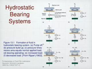
Magnetic Bearings and Their Applications Magnetic bearings take radial or thrust loads by utilizing a magnetic field to support the shaft rather than a mechanical force as in fluid film or rolling element bearings. Advantages over Ball Bearings • No wear • Long life • Elimination of oil supply • Vibration control • Very low power consumption • Diagnostic capability
Magnetic Bearings and Their Applications Energy Storage Flywheel Systems (Electromechanical Batteries) • Transferring energy of various • forms into rotational inertial • energy of the flywheel: • solar energy • wind power • inertial energy of a car • ···
Magnetic Bearings and Their Applications Energy Storage Flywheel Systems (Electromechanical Batteries)
Magnetic Bearings and Their Applications Artificial Heart Pumps
Magnetic Bearings and Their Applications Turbines Magnetic spindles (For high speed grinding)
Nonlinearities in Magnetic Bearings Balance beam magnetic bearing test rig Dynamic equation:
Nonlinearities in Magnetic Bearings A conventional current biasing strategy: Linearization at A constrained control problem: • Input constraint: • State constraint: Let
Nonlinearities in Magnetic Bearings Normalization: Let and Then, Null controllable region: Maximal possible stability region:
Nonlinearities in Magnetic Bearings Description of and : Let and be the eigenvalues of Denote Proposition 1. 2.
Nonlinearities in Magnetic Bearings Dependence of on :
Nonlinearities in Magnetic Bearings Stabilizing controllers : Proposition Under the feedback law is the stability region.
Nonlinearities in Magnetic Bearings Performance vs : Proposition Under the feedback law 1. The convergence rate increases as is increased; 2. The disturbance is better rejected as is increased; Disadvantage of using large : Power consumption
Nonlinearities in Magnetic Bearings Experimental results, :
Nonlinearities in Magnetic Bearings Experimental results, :
Nonlinearities in Magnetic Bearings Experimental results, convergence rates under :
Modeling of Flexible Rotors Flexible rotor on magnetic bearings test rig:
Modeling of Flexible Rotors Finite element method:
Bending Modes Measured Frequency(Hz) Calculated Frequency(Hz) Difference (%) 1 153.0 152.85 -0.10 2 310.5 310.40 -0.03 3 614.0 613.54 -0.07 4 1067.5 1070.38 0.27 5 1455.0 1473.97 1.30 Modeling of Flexible Rotors Experimental verification:
Modeling of Flexible Rotors Model order reduction:
Modeling of Flexible Rotors Gyroscopic effects : Uncertainty characterization:
Robust Control Design Possible methods : • control design … not successful • LPV control design … computationally not implementable (yet) • synthesis … treating rotor speed p as uncertainty, • valid for a segment of speed range • Piecewise synthesis … switching between controllers, • bumpy transience, bumpless transfer?
Robust Control Design Piecewise synthesis :
Robust Control Design Switching between two controllers :
Robust Control Design Bumpless transfer : Main Idea: Build an observer that estimates the off line controller state from the on line controller output Use the estimate state as the initial state at time of switching As a result,
Robust Control Design Bumpless transfer : experimental results (12,000 rpm)
Controller Implementation Current hardware and software setup : • RT-Linux is used to support real-time computation. • A 700 MHz Intel P III with a single 5 channel A/D card and a single 5 channel D/A card is the necessary hardware currently implemented • RTic-Lab serves as the software operating platform for controller testing
Controller Implementation Larger computational capacity for LPV controllers and/or higher rotor speeds : • Parallelization, multiprocessor version of the RT-Linux • Use of SSE instructions supported in the Pentium III and IV • Use of the higher-speed commodity processors
Issues to Be Addressed Balancing : mechanical and/or by magnetic bearing Unbalance force:
Issues to Be Addressed Model reduction of gyroscopic systems : This will be critical for the design and implementation of LPV controllers
Issues to Be Addressed Voltage saturation : Rotor dynamics Dynamics of the circuits
Issues to Be Addressed Control objective: To keep the rotor centered in the presence of disturbance d. In steady state, it is required that
Issues to Be Addressed Power loss reduction by bearing and control design Observation • Larger biasing currents in general lead to better performance • Larger biasing currents incur more power loss Approach For a given bias level, optimize the performance by appropriate control design