725
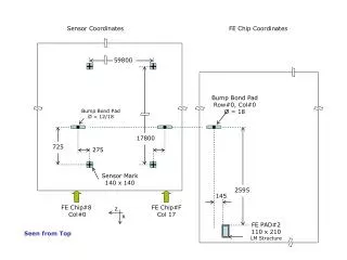
Sensor Coordinates. FE Chip Coordinates. 59800. Bump Bond Pad Row#0, Col#0 Ø = 18. Bump Bond Pad Ø = 12/18. 17800. 725. 275. Sensor Mark 140 x 140. 2595. 145. FE Chip#8 Col#0. FE Chip#F Col 17. z. x. FE PAD#2 110 x 210 LM Structure. Seen from Top. Sensor. M2. M1.

725
E N D
Presentation Transcript
Sensor Coordinates FE Chip Coordinates 59800 Bump Bond Pad Row#0, Col#0 Ø = 18 Bump Bond Pad Ø = 12/18 17800 725 275 Sensor Mark 140 x 140 2595 145 FE Chip#8 Col#0 FE Chip#F Col 17 z x FE PAD#2 110 x 210 LM Structure Seen from Top
Sensor M2 M1 M2-W8-X M3 M4 M3-W8-X M3-W8-Z FE PAD#2 110 x 210 LM Structure M3-WF-Z M4-WF-Z M3-WF-Z z FE Chip#8 FE Chip#F x Seen from Top W8 WF
Wire Bond to Sensor Mark • In the table on the right there are the distances from each of the 4 sensor mark to the first wire-bond pad of the 8 FE chips opposite to the barrel pigtail. • The FE chips are: FE#8,…, FE#F. • The reference system is the one used in the stave.
Definition of module pitch in Z Sensor Marks PITCH PITCH PITCH PITCH M1A M0 M1C M2C M2A z