Download
1 / 72
750 likes | 1.07k Vues
Unit Ten: Reflection and Refraction of Light. John Elberfeld JElberfeld@itt-tech.edu 518 872 2082. Schedule. Unit 1 – Measurements and Problem Solving Unit 2 – Kinematics Unit 3 – Motion in Two Dimensions Unit 4 – Force and Motion Unit 5 – Work and Energy

E N D
Unit Ten:Reflection and Refraction of Light John Elberfeld JElberfeld@itt-tech.edu 518 872 2082
Schedule • Unit 1 – Measurements and Problem Solving • Unit 2 – Kinematics • Unit 3 – Motion in Two Dimensions • Unit 4 – Force and Motion • Unit 5 – Work and Energy • Unit 6 – Linear Momentum and Collisions • Unit 7 – Solids and Fluids • Unit 8 – Temperature and Kinetic Theory • Unit 9 – Sound • Unit 10 – Reflection and Refraction of Light • Unit 11 – Final
Chapter 10 Objectives • Define and explain the concept of wave fronts and rays. • Explain the law of reflection and distinguish between regular (specular) and irregular (diffuse) reflections. • Explain refraction in terms of Snell's law and the index of refraction, and give examples of refractive phenomena. • Describe total internal reflection and understand fiber optic applications. • Explain dispersion and some of its effects.
Reading Assignment • Read and study College Physics, by Wilson and Buffa, Chapter 10, pages 322 to 340 • Week 11 is your scheduled final exam on Chapters 1-10 • The final is 40 multiple choice questions worth 2.5 points each • Questions include problems, definitions
Written Assignments • Do the homework on the handout. • You can work on other problems that build up to the required problems • Answers to odd-numbered problems and Follow-up Exercises are in the back of your book • The Student Study Guide explains some solutions in detail • You must show all your work, and carry through the units in all calculations • Use the proper number of significant figures and, when reasonable, scientific notation
Part 1 : Reflection and Refraction of Light • We now turn from our study of sound waves to the study of another type of wave, light. • In contrast to sound, in which the waves consist of pressure or density differences in matter and require matter to propagate, light waves consist of alternating electrical and magnetic fields and need no matter to propagate. • Therefore, light waves are called electromagnetic radiations.
Nature of Light • Light can be thought of as both a wave (electro-magnetic wave) and a particle (photon). • In this section, we treat light strictly as a wave with a frequency (f), period (t), wavelength (λ) and velocity (v) • V = f λ f = 1 / t
Electromagnetic Waves • Light forms a portion of the electromagnetic spectrum, which includes gamma waves with wavelengths shorter than the size of an atomic nucleus up to radio waves with wavelengths longer than a mile. • In this week’s lessons, we will be concerned with the visible and near-visible wavelengths of the electromagnetic spectrum.
Light • Sound is a mechanical wave and requires a medium to propagate. • Light, on the other hand, is a wave that propagates in a vacuum and consists of time-varying electric and magnetic fields. • Light consists of the visible (and near-visible) parts of the electromagnetic spectrum.
Wavelengths • The electromagnetic spectrum includes waves such as radio waves, radar waves, microwaves, and infrared radiation. • These waves have wavelengths longer than visible light. • It also includes ultraviolet rays, X-rays, and gamma rays that have wavelengths shorter than visible light. • Infrared waves with wavelengths just longer than visible and ultraviolet waves with wavelengths just shorter are also commonly referred to as "light" even though they are not visible to human eyes. • Electromagnetic radiation - particularly with wavelengths shorter than visible light - is frequently said to be made up of particles with zero mass, called photons.
Speed of Light • All parts of the electromagnetic spectrum travel at 3.00 x 10⁸ m/s in a vacuum and at a lower speed in material. • 299 792 458 m/s is more accurate but totally unnecessary in your calculations
Geometric Optics • When studying light, you can ignore the wave properties of diffraction and interference, and assume that light travels in a straight line. • You can also ignore the atomic interactions between light and transparent materials, and assume that light travels through transparent materials at reduced speeds. • These simplifications form the basis of geometric optics, in which phenomena such as the reflection and refraction of light are explained in terms of wave fronts and rays.
Wave Fronts • In geometric optics, you assume that light emanates from a point source in a spherical wave. • A wave front is an imaginary line showing the location of the crest of the wave. • To be more precise, it can also be referred to as the line that represents all parts of a wave that are in phase, since you can choose the trough of the wave or any point in between the crest and the trough. • The distance between the wave fronts is known as the wavelength.
Wave Nature of Light • If we drop a stone into still water, a circular wavefront travels away from the origin of the disturbance. • Waves and wave fronts in water are shown below: • In the case of light, wave fronts are spherical in shape.
Wave Fronts • A wave front is defined by adjacent points on a wave that are in phase, such as those along wave crest and troughs • Near a point source, the waves are circular in three dimensions • Very far from the point source, the wave fronts are approximately linear or planar. • A line perpendicular to a wave front in the direction of the wave’s propagation is called a ray.
Rays • A ray is an imaginary line emanating from a point source, which indicates the direction that the light wave is moving in.
Reflection • Reflection of light is an optical phenomenon of enormous importance. • If light were not reflected to our eyes by objects around us, we wouldn’t see the objects at all. • Reflection involves the absorption and reemission of light by means of complex electromagnetic vibrations in the atoms of the reflecting medium.
Rays • Thankfully, however, the phenomenon is easily described by using rays. • A light ray arriving at and hitting a surface is called the incident ray. • After hitting the surface, the departing ray is called the reflected ray.
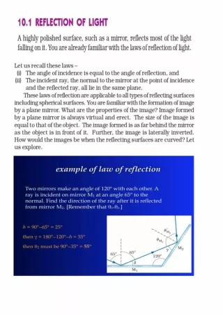
Law of Reflection • The law of reflection is defined as the principle that when a ray of light, radar pulse, or the like, is reflected from a smooth surface the angle of reflection is equal to the angle of incidence, and the incident ray, the reflected ray, and the normal to the surface at the point of incidence all lie in the same plane.
Θi = Θr • This law applies to a single ray that strikes any surface and reflects from it. • The angle of incidence Θi is the angle an incident ray makes with a line that is perpendicular (normal) to the surface. • The angle of reflection Θr is the angle the reflected ray makes with the perpendicular (normal) of the surface. • As shown on the graphic, the angle of incidence is equal to the angle of reflection: • Θi = Θr
Specular versus Diffuse Reflection • While the law of reflection always holds, the reflected angle is not always the same over large areas of a surface because light does not keep a constant angle over large areas. • This results in regular and irregular reflection. • When light rays are reflected from a smooth surface, the reflected rays will be parallel, the reflection is said to be regular or specular – you can see an image in the reflections. • When light rays reflect from a rough surface, the reflected rays will not be parallel and no image will be visible in the reflection because the reflected light travels in various directions. • Note that the law of reflection still applies locally to individual rays and small areas of the surface.
Refraction • Reflection and refraction both occur whenever a wave strikes the boundary between two media. • We have already discussed reflection; refraction refers to the change in the direction of a wave at a boundary where the wave passes from one transparent medium into another. • Refraction deals with the portion of the incident beam that penetrates into the second medium from the first.
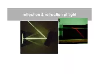
Examples • The graphic on the screen shows how an incident beam of light strikes a prism and forms two beams at the surface: a refracted beam and a reflected beam. • When the refracted beam strikes the inner surface of the prism, it produces two more beams, a refracted beam, which is parallel to the original incident beam, and a reflected beam. • The reflected beam strikes the upper inner surface and produces two more beams, a refracted beam parallel to the first reflected beam and a reflected beam that is not visible in the picture.
Refraction Normal Air Θrefl Θi Water Θrefr
Spearing a Fish Normal Air Θi Θrefl Water Θrefr
Refraction • The speed of light in transparent media is generally less for denser media and is always less than it’s speed in vacuum - 3x10⁸ m/s. - for air, only slightly less. • It is something of a misnomer to call the glass a medium through which light travels, since light travels in a vacuum and does not require a medium. • The index of refraction (n) of a medium is the speed of light in a vacuum (c) divided by the speed of light in the medium (v): • n = c / v
Index of Refraction • The index of refraction of various materials is shown in the table on the screen. • The wavelength is specified because the index of refraction of a material varies with the wavelength. • n = c/v
Practice • Light from a laser with a wavelength of 632.8 nm travels from air into water. • What are the speed and wavelength of the laser light in water? • Note: Frequency and period do NOT change • nwater=1.33 from table • n = c / v v = f λ f = 1 / t
Calculations • nwater = c / vwater • 1.33 = (3x10⁸m/s) / vwater • vwater = (3x10⁸m/s) / 1.33 = 2.26x10⁸m/s • vair = f λair • 3x10⁸m/s = f x 632.8 nm (n = 10-9) • f = (3x10⁸m/s) / 632.8 x 10⁻⁹ m = 4.74x10¹⁴ Hz • vwater = f λwater • 2.26x10⁸m/s = 4.74x10¹⁴ Hz λwater • λwater = 2.26x10⁸m/s / 4.74x10¹⁴ Hz = 4.77x10⁻⁷m • λwater = 477nm
Refraction • The diagram shows that when a beam of light or a single ray is incident upon a boundary between two media, the beam or ray changes direction. • This can be understood from the principle that every point on a wave front can act as a source of new circular waves called wavelets. • Since the wave front strikes the boundary at an angle, the wavelets enter the new medium at different times and one end of the wave front slows down before the other.
Snell’s Law • As a result, the wave changes direction. • This change in direction can be calculated from Snell's law: • sinΘ1 / sinΘ2 = n2/n1 • The angles are, as usual, measured from the normal.
Snell’s Law • A line of six marching soldiers represents a wave front. • When the soldiers reach the muddy patch their speed decreases. • Thus, the distance between the lines of marching soldiers decreases. (v = f λ) • Since one end slows down before the other, the direction of the marching soldiers changes. • The angle of change is determined by the ratio of the speed in one medium to the speed in the other medium.
More Illustrations • This diagram shows the bending of light as it passes from a less dense medium (like air) into a more dense medium (like glass.) • n2>n1 • Θ2<Θ1
Another Illustration • This diagram shows the bending of light as it passes from a more dense medium (like glass) into a less dense medium (like air.) • n2<n1 • Θ2>Θ1
Normal Air 37º glass ??º Practice • A ray of light is incident on a piece of crown glass at an angle of 37.0º relative to the normal. (Going from air into the glass) • n =1.52 from table • What is the angle of refraction?
Calculations • sinΘ1 / sinΘ2 = n2/n1 • sin(37º) / sin Θ2 = 1.52 / 1 • sin Θ2 = sin(37º) / 1.52 = .396 • Θ2 = sin-1 (.396) • Θ2 = 23.3º
Examples • The following diagrams show three examples of light rays emitted from three objects under water: a fish, a coin, and a chopstick. • The fish, chopstick, and coin reflect the light in the room, thus enabling you to see them. • However, you cannot see the actual location of these objects under water. • This is because when the light rays hit the surface of the water, they travel from a medium of high refractive index (water) to a medium of low refractive index (air). • This causes the rays to bend away from the perpendicular direction (normal) and the objects appear to be placed at locations different from their actual ones.
Fish Example • The light is refracted, and because we tend to think of light as traveling in straight lines, the fish is NOT where we think it is
Chopstick • The chopstick appears bent at the air-water boundary. If the cup is transparent, we see another type of refraction.
Coin • Because of refraction, the coin appears to be closer than it actually is
Practice • Bob and Bill are 3m from a mirror. Bob shines a flashlight and the reflection hits Bill in the face. The angle the light makes is 67º from the normal to the mirror. • How far away from Bob is Bill?
67º 3m Diagrams 3m 67º x
67º 3m Trig • TanΘ = x / 3m • x = 3m tan(67º) • x = 7.07 m • The distance is twice that or 14.14 m 7.07m
Mirrors • Two plane mirrors, M1 and M2, are placed together as illustrated in the figure. • If the angle between the mirrors is 75º and the angle of incidence of a light ray incident on M1 is 35º, what is the angle of reflection from M2?
Diagrams • 180º in each triangle • 90º in a right angle • 40º final angle ofreflection 75º 55º 35º 50º 35º 40º 40º
Normal Air 50º Plastic 35º Problem • Find nplastic
Calculations • sinΘ1 / sinΘ2 = n2/n1 • sin(50º) / sin(35º) = n2 / 1 • n2 = sin(50º) / sin(35º) • n2 = 1.33
Internal Reflection • When you are under water, have you ever looked up toward the surface and tried to see what was going on above the water surface? • The view may have surprised you! • It looks like the water surface is a huge rippling mirror with a hole letting you see through directly above you. • Now that we have studied the basic laws of geometric optics, let us look at some more concepts related to light.
Total Internal Reflection • When an incident light ray strikes a boundary between two media, two rays are created: a refracted ray and a reflected ray. • Consider the case when an incident ray goes from a medium with a higher refractive index (n1) to a medium with a lower refractive index (n2); that is n1 is greater than n2. • In this case, the refracted angle is farther from the normal than the incident ray. Θ1