Download
1 / 22
590 likes | 1.58k Vues
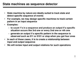
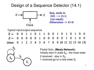
Design of a Sequence Detector (14.1). Seq. ends in 101 --> Z=1 (no reset) Otherwise--> Z=0. Typical input/output sequence. Partial Soln. (Mealy Network) : Initially start in state S 0 - the reset state 0 received - stay in S 0 1 received go to a new state S 1.

E N D
Design of a Sequence Detector (14.1) Seq. ends in 101 --> Z=1 (no reset) Otherwise--> Z=0 Typical input/output sequence Partial Soln. (Mealy Network): Initially start in state S0 - the reset state 0 received - stay in S0 1 received go to a new state S1
Design of a Sequence Detector (14.1) Seq. ends in 101 --> Z=1 (no reset) otherwise--> Z=0 Partial Soln.: 0 received in S1 - go to a new state S2 1 received in S2 seq. (101) rec’d (Z=1) -cannot go back to S0 (no reset) -go back to state S1 since last 1 could be part of a new seq. Final State Graph: 1 received in S1 - stay in S1 (seq. restarted) 0 received in S2 seq. (00) rec’d -must reset to S0
Design of a Sequence Detector (14.1) Seq. ends in 101 --> Z=1 (no reset) otherwise--> Z=0 Convert State Graph to State Table: Represent the three states with two FF’s A and B to obtain the transition table.
Design of a Sequence Detector (14.1) Plot next state and Z maps from transition table
Design of a Sequence Detector (14.1) From the next state and Z maps we obtained: A+ = X’B, B+ = X, Z = XA If D FF’s are usedDA =A+, DB =B+ which leads to the network:
Design of a Sequence Detector (14.1 Moore) Seq. ends in 101 --> Z=1 (no reset) otherwise--> Z=0 For the Moore Network: When a 1 is rec’d to complete seq. (101) -must have Z=1 so must create a new state S3 with output Z=1 Note the seq. 100 resets the network to S0 Final State Graph
Design of a Sequence Detector (14.1 Moore) Convert State Graph to State Table: Represent the four states with two FF’s A and B to obtain the transition table. FF input eqns. can be derived as was done for Mealy network.
Mealy Sequential Network (14.2) Seq. ends in 010 or 1001 --> Z=1 Otherwise --> Z=0 Partial State Graph -gives Z=1 for seq. 010
Mealy Sequential Network (14.2) Seq. ends in 010 or 1001 --> Z=1 Otherwise --> Z=0 Partial State Graph -additional states for seq. (1001)
Mealy Sequential Network (14.2) Seq. ends in 010 or 1001 --> Z=1 Otherwise --> Z=0 Final State Graph -takes into account all other input sequences
Moore Sequential Network (14.2) Z=1 if total no. of 1’s received is odd and at least two consecutive 0’s rec’d
Moore Sequential Network (14.2) Z=1 if total no. of 1’s received is odd and at least two consecutive 0’s rec’d
1 1 Final graph includes other seq.
Soln.: (A blank space above the slash indicates that the network has no other Input than the clock.) The repeating part of the sequence is generated using a loop.
States are based on the previous input pair. Don’t need separate states for 00, 11 since neither input starts a seq. which leads to an output change. However, for each previous Input, the output could be 0 or 1, so we need six states.
Example 3 cont’d We can set up the state table shown below. e.g. S4 row: If 00 rec’d the input seq. has been 10,00 so output does not change and we go to S0. If 01 rec’d the input seq. has been 10,01 so output changes to 1 and we go to S3. If 11 rec’d the input seq. has been 10,11 so output changes to 1 and we go to S1. If 10 rec’d the input seq. has been 10,10 so output does not change and we stay in S4. 01,11 --> 0 10,11 --> 1 10,01 --> change
Example 3 cont’d 01,11 --> 0 10,11 --> 1 10,01 --> change
A Converter for Serial Data Transmission: NRZ-to-Manchester • Coding schemes for serial data transmission • NRZ: nonreturn-to-zero • NRZI: nonreturn-to-zero-inverted • 0 - same as the previous bit; 1 - complement of the previous bit • RZ: return-to-zero • 0 – 0 for full bit time; 1 – 1 for the first half, 0 for the second half • Manchester