Download

1 / 69
720 likes | 1.07k Vues
Moisture Sensitive Devices A Real Production Problem. Background. Moisture and Surface Mount Components do not mix Plastic packaging material very often is permeable to moisture

E N D
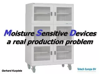
Moisture Sensitive Devices • A Real Production Problem
Background • Moisture and Surface Mount Components do not mix • Plastic packaging material very often is permeable to moisture • If moisture permeable plastic packaging material levels become critical, component damage may occur when subject to reflux temperature (popcorning) • Moisture induced failures are often undetectable, causing malfunction within 2 and 6 months • Higher processing temperatures of unleaded solder will exacerbate the problem
Lead Free and Popcorning Quelle: Intel
Popcorning • The epoxy moulding compound used in most plastic encapsulated devices is hygroscopic • While processing, temperatures up to 260º C are applied • Fast ramps and high temperatures prevent moisture from escaping
Popcorning • This leads to delaminating the encapsulated interface of the die, resulting in a gas bubble • This is not always visually apparent
Popcorning • Exceeding the technical elastic limit results in cracking of the plastic packaging, water vapour escapes with a sudden burst • The plastic packaging has a „leak“ permeating oxygen slowly destroys the components
Popcorning Example 1 • BGA device, showing crack between fibreglass substrate and plastic body moulding
Popcorning Example 2 • QFP device, showing crack on top of plastic body moulding
Popcorning Example 3 • Micro section through BGA device, showing delaminating and crack through conductive adhesive and fibreglass substrate
Popcorning Example 4 • BGA device, showing crack between fibreglass substrate and plastic body moulding
Popcorning Example 5 • QFP device, showing crack on the underside of the plastic body moulding
IPC-Levels for IC`s Quelle: IPC
IPC-Levels for IC`s Quelle: Intel
Component Humidity Quelle: Intel
Absorption Quelle: Intel
Absorption Quelle: Intel
Traditional Prevention • Historically components and printed control boards have been backed to remove moisture • Typically temperatures from 40 to 125 C and times of between 1 hour and 1 week have been used • This adds time and a monetary cost to production • Backing is still possible, only according to IPC spec
Problems with Baking • Surface solder ability is degraded • Growth of inter metallic layers is promoted, also with low temperature (40 degree C • Baking is only possible one time (IPC) • Ovens can be expensive to run • They take up valuable space on the production floor
Solder Ability SOIC 14 Chip, 60/40 Sn/Pb alloy, type R flux, as received
Solder Ability SOIC 14 Chip, 60/40 Sn/Pb alloy, type R flux, 4 hours @ 100 C
Solder Ability SOIC 14 Chip, 60/40 Sn/Pb alloy, type R flux, 4 hours @ 100 C SOIC 14 Chip, 60/40 Sn/Pb alloy, type R flux, as received
Inter Metallic Growth • Total inter metallic thickness has shown to increase by approximately 50% when baking at 125 C is used for 4 days • In the case of a copper metallisation, this is mainly the Cu6 Sn5 layer but all layers are effected • Inter metallic growth is a function of time and temperature • The thicker inter metallic layers can lead to a reduction in solder joint integrity and in extreme cases reduce solder ability
Alternative Prevention • Use a Drying Cabinet No reduction of solder ability as no heat is involved Oxidisation is prevented by diminishing humidity All moisture is removed by a recycling desiccant drying system Lower operating cost (compared to baking) Efficient use of factory floor space
Variety of Dry Storage • Moisture Barrier Bags • Nitrogen Cabinets • Dry Air Boxes • Desiccant Dry Cabinets
Pros / Cons of MBB Storage Cons • Bags can/do remain unsealed for extended periods • Silica Gel packets used ‘’past their prime’’ • Silica Gel packets improperly stored • Labor intensive Pros • Inexpensive start up, little investment required
Pros / Cons of Nitrogen Cabinets Cons • Often poorly maintained • Rarely monitored for effectiveness • Costly to operate • Installing is necessary • Not available everywhere • Very pure N2 is needed to dry components, expensive!! • Can hardly dry components Pros • N2 often available • N2 cabinets familiar
Comparison of Costs using N² · Assumptions Costs of N² ~ 0.19 € / m³ Power costs ~ 0.06 € / KWh average N² consumption ~ 25 L / min Purchase costs of Totech Dry Cabinet ~ 7 600.00 € · Arising expenses from a N² cabinet Consumption : 25 l / min, i.e. 1 080 000 l / month, i.e. 1080 m³ / month Costs: 205,20 € / month, i.e. 2462.40 € / year · Arising expenses from a Totech Drying Cabinet Consumption : 0.056 kW / h, i.e. 40.32 kW / month Costs : 2.42 € / month, i.e. 29.09 € / year Saving of costs within one year: 2 433.31 € This is equivalent to 37.5 months refinancing (Purchase costs: 7 600.00 €) only by the N² consumption of a nitrogen cabinet (~ 3 years) (The calculation excludes installing the nitrogen cabinet and leasing costs for N² bottles.)
History of Drying Cabinets 1974 - First auto-recycling dry cabinet developed for commercial use utilizing Silica Gel, regularly being dried by a heating system 1976 First use of synthetic zeolites (as molecular sifter ) in dry cabinet designs, replacing Silica Gel 1982 New dryer design capable of managing ultra-low humidity levels, patented(Totech, Japan) 1987 Texas Instruments, with primary applying of ultra-low humidity dry cabinets for MSD storage. Before that, dry cabinets were only used for the optics industry and consumer goods
Pros / Cons of Desiccant Dry Cabinets Pros • Dries without use of heat • Fast de-humidification • Zero maintenance • Constantly monitored for effectiveness • Low cost operation • Air tight • Mobile Cons • Higher initial investment required
Recommendation for Time of Drying At the same temperature, the drying time is equal to backing time according to IPC reference. HSD-Series SDE-Series
Dry Cabinet Acceptance • App. 200.000 Dry Cabinets sold every year extensive residential use in Asia • App. 10.000 ‘less than 5% RH’ cabinets sold every year worldwide • A total of 8-10 desiccant dry cabinet manufacturers worldwide • Increasing demand in Europe (lead-free)
Dry Cabinet Suppliers • 8-10 large suppliers worldwide • Cabinet should at least go to 5% RH • Great majority of cabinets built for the residential market (i.e.. 30-50% RH) • The demand for ultra-low humidity is growing
Various Dry Cabinet Applications • CSP, BGA, QFP etc • Printed Circuit Boards • Wafers • Ceramics • Crystal Resonator • Optical Fiber, CCD etc • (LCG) Liquid Crystal Glass
IPC/JEDEC 033a Application Dry Cabinet at 10% RH • MSD packages not sealed in a MBB may be placed in a dry atmosphere cabinet, maintained at not greater than10%RH. These dry cabinets should not be considered a MBB • Storage of MSD packages in these dry cabinets should be limited to a maximum time per Table 7-1. If the time limit is exceeded they should be baked according to Table 4-2 to restore the floor life
IPC/JEDEC 033 Application Dry Cabinet at 5% RH • MSD packages not sealed in a MBB may be placed in a dry atmosphere cabinet, maintained at not greater than 5% RH • Storage in these dry cabinets may be considered equivalent to storage in a MBB with unlimited shelf life
Functional Principles • An interlocked fan causes the air to circulate through the dry unit • While passing through the dry unit moisture in the air is absorbed by the zeolite desiccant • During periodic rejuvenating of the zeolite desiccant by heating, the absorbed humidity is evaporated and exhausted through the external shutters of the dry unit
Function of Dry Unit (Moisture being exhausted during recycling period)
Zeolite • Synthetically produced zeolite A • 47% open space • High rate of absorption at low RH levels • Excellent ability to regenerate
Functional Principle To ensure a minimal inflow of outside ambient air the interlocked fan is stopped automatically when a door is opened (Extra Feature on Super-Dry)
Functional Principle After the doors are closed, the fan beginsoperating again to accelerate the moisture absorption inside the air tight Drying Cabinet
Calibrating Calibrating is possible by exchanging the complete Humidity Sensor
Maintenance Recommendation • Running time of the interlocked fan is interrupted (30% on). Still the fan is subject to abrasion, esspecially concerning the bearings • To garantee good functioning the fan must be changed after the indicated time of operational performance (Triple operational performance by interruption enables about 10 years of functioning)
Basic Requirements • Must recover within an ‘‘acceptable‘‘ period of time after being accessed • Must maintain a constant RH level once recovery is complete