Download
1 / 17
170 likes | 346 Vues
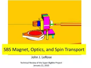
Beam Splitter / State Selector, Polarizing Magnet, and Spin Flipper. WBS 1.2.1, 1.2.2, 1.2.3: Splitter/State Selector Main Body WBS 1.2.4, 1.2.5, 1.2.6: Polarizing Magnet WBS 1.3.1, 1.3.2, 1.3.3: Spin Flipper. Takeyasu Ito University of Tennessee/Oak Ridge National Laboratory.

E N D
Beam Splitter / State Selector, Polarizing Magnet, and Spin Flipper • WBS 1.2.1, 1.2.2, 1.2.3: Splitter/State Selector Main Body • WBS 1.2.4, 1.2.5, 1.2.6: Polarizing Magnet • WBS 1.3.1, 1.3.2, 1.3.3: Spin Flipper Takeyasu Ito University of Tennessee/Oak Ridge National Laboratory EDM Cost and Schedule Review February, 2005
SNS FNBP UCN Beamline and EDM Experiment Layout Takeyasu Ito
Purpose, Functions and Design Goals • Split the beam into two, to feed the two measurement cells • Polarize neutrons • Flip the polarization of each beam independently • Maximize the beam delivered to the measurement cells Takeyasu Ito
Principle of Polarizer/Splitter with Polarizing Supermirror Polarizing supermirror: One spin state: reflected up to the critical angle cpsm The other spin state: transmitted at all angles In order for one spin state to be 100% reflected, If the input guide has m=1.5, and PSM has m=2.4, then = 14mrad. Need 10 m for 15cm wide guide Takeyasu Ito
One Possible Layout m=2.4 polarizing supermirror coated on thin Si wafer Diverging horn (7 m) Polarizer/Splitter (14 m) 12 cm wide, m=3.5 straight guide (buried under shielding) 30 cm wide, m=1.5 straight guide ( 2m) Rudimentary (2-dimentional) Monte Carlo study indicated 30% transmission and 90% polarization. Takeyasu Ito
Cost Estimate - Overview (WBS 1.2) • Design • $63,200 + $27,176 • Procurement • $953,940+ $410,194 • Installation • $12,640 + $5,435 Total + Contingency= $1,029,780 +$442,805 Note: The diverging horn is not included in the budget although it is not included in the FNPB baseline. If this is proven to be beneficial for other experiments at the FNPB UCN line, we expect some kind of cost sharing between FNPB and EDM. Takeyasu Ito
Cost Estimate - Design (WBS 1.2.1) • Conceptual design/Monte Carlo simulation • Physicist x 100hrs = $0 • Shop drawings • Engineer x 200hrs = $31,600 • Preparation of equipment spec • Engineer x 200hrs = $31,600 Total + Contingency = $63,200 + $27,176 Takeyasu Ito
Cost Estimate - Procurement (WBS1.2.2) • Preparation for procurement • Physicist x 30hrs = $0 • Engineer x 30hrs = $4,740 • Splitter/State Selector • Engineering Design + Fabrication = $949,200 (=$840,000+13% overhead) Total + Contingency = $953,940+ $410,194 Takeyasu Ito
Splitter/State Selector System • Basis for estimate • Supermirror guides $30k/m for m=3.5 * Note: price of coating goes as m4 • Si wafer $30 / 4-inch disk * From semiconductor industry, roughness ~ 5Å (source J.J.Ferme from Seso) • Cost estimate • $30k/m x 14m x 2 = $840 k * Factor 2 for coating Si wafer and constructing more complicated system than straight guide Takeyasu Ito
Example: SNS FNPB UCN Beamline • Guides = $25.1K/m • Vacuum housing=$3.84K/m • Support and Adjustment fixtures=$790/m *Based on quote from Swiss Neutronics on FNPB UCN beamline with the following parameters: • The guide size is 100mm x 120mm • The guide will have m=3.5 all sides • The guide is straight • The guide has a total length of 30m Takeyasu Ito
Cost Estimate - Installation (WBS1.2.3) • Installation • Technician x 80hrs = $12,640 • Oversight • Physicist x 40hrs = $0 Total + contingency = $12,640 + $5,435 Takeyasu Ito
Cost Estimate - Contingencyfor WBS 1.2.1-3 • Technical • Risk factor=10% • Risk weight=2 • Cost • Risk factor=15% • Risk weight=1 • Schedule • Risk factor=8 Total percentage contingency = 43% Takeyasu Ito
Estimate for Duration • Design: 88 days + 43% float • Conceptual design: 100 hours • Shop Drawing: 200 hours • Preparation of equipment spec: 200hours • Procurement: 1 year + 43% float • Installation: 14 days + 43% float Takeyasu Ito
Cost and Schedule Estimate for Polarizing Magnet (WBS 1.2.4-6) • Design • Design work by physicists • $0 • 255 days • Procure • $158,200+ $68,026 • 183 days • Install • $12,640 + $5,435 • 21 days Takeyasu Ito
Cost and Schedule Estimate for Spin Flipper (WBS1.3.1-3) • Design • Design work by physicists • $0 • 21 days • Procure • Flippers: $40,000 • Power supplies, etc: $36,000 • Total: $85,880 + $36,928 • 183 days • Install • $6,320 + $2,718 • 14 days Takeyasu Ito
Summary • Splitter/State selector (WBS 1.2) • $1,200,620 +$516,266 • 662 days • Spin Flippers (WBS 1.3) • $92,220 + $39,646 • 317 days Takeyasu Ito