Download
1 / 20
200 likes | 393 Vues

E N D
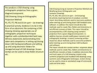
CAD Drawing Using an Isometric Projection Method and Modifying Given Orthographic andIsometric DrawingsP3, P5, M1, M3 and D2 (In part – 2nd drawing)An activity requiring learners to produce a written report describing methods used to overcome problems when starting up and closing down CAD hardware and software. In addition the report should describe methods used to create files, folders and directories to aid efficient recovery of data. This report should be accompanied by a CAD drawing using isometric projection from a given diagram/component. In addition learners should modify given isometric and orthographic drawings. A report containing writtenresponses about methods used to overcome problems when starting up and closing down CAD hardwareand software.The report should also contain written responses about methods used to create files, folders and directories to aid efficient recovery of data. In addition electronic files and hard copies of a CAD drawing created using isometric projection and modified CAD drawings using isometric and orthographic techniques. Screen dumps can be used to show an annotated range of commands used and time taken. You produce a CAD drawing using orthographic projection from a given diagram/component. CAD Drawing Using an Orthographic Projection Method P1, P2, P7, P8 and D2 (In part – 1st drawing) A practical activity. Evidence is to be in the form of an electronic file containing a CAD drawing showing appropriate use of orthographic projection techniques together with a plotted/printed hard copy. Witness statements demonstrating time taken and competence in setting up/closing down CAD hardware/software and setting up and using electronic folders for storage/retrieval of CAD drawings. Screen dumps can be used to show folder structure etc.
P1:Start up a CAD system, produce and save a standard drawing template and close down CAD hardware and software in the approved manner Starting from when the computer system is switched on, produce a flow chart showing all the stages of : Print screen & paste each stage into WORD. Starting up a CAD system Opening a drawing template you have previously created. Saving the template Close down the software. M1: you should think of at least 4 things that could go wrong when starting up or closing down the CAD system and what you would if things went wrong. To achieve this grade you need to describe how you overcome problems encountered in starting up. List these 4 problems in detail.
P1:Start up a CAD system, produce and save a standard drawing template and close down CAD hardware and software in the approved manner.
P1:Start up a CAD system, produce and save a standard drawing template and close down CAD hardware and software in the approved manner.
P5 Use CAD commands to modify a given orthographic and isometric drawing
P7: Set up an electronic folder for the storage and retrieval of information To create an Electronic folder I decided to show the steps I would use to save a file in an Electronic folder
P8 store, retrieve and print/plot seven CAD-generated or modified drawings.
M1 identify and describe four methods used to overcome problems when startingup and closing down CAD hardware and software You can complete a table similar to the example above or produce a flow chart by print screening showing all the stages of : Starting up a CAD system Opening a drawing template you have previously created Saving the template Closing down the software
D1 justify the use of CAD for the production of a range ofdrawing types Justify the use - that means you need to explain why CAD is a useful tool. Give examples of how easy it is to use. • Be able to modify • Edit • Save • Transmit to CAM and make; in other words
P2: Produce a CAD drawing using an orthographic projection method. Using Cad software e.g. Prodesktop draw the object shown in Figure 10.4 to full size. You should use the template you created in the worked example in 10.1.1; you will also need to add the centre lines, hidden lines and dimensions. Draw the object in first angle projection. Save the completed drawing as assessment 10.4. You will need to make sure all the views line up properly. To help you do this, it might be useful to construct guidelines. • Explain how you used each of the drawing commands. • Compare how you used each command with its use on the other drawings you have completed. • Compare the alternative, non-CAD methods of producing drawings with the use of CAD, and explain why you think CAD is the most useful in each case.
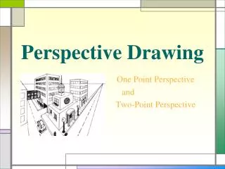
P3: Produce a CAD drawing using an isometric projection method.
M2 Describe the drawing commands used across the range of drawing types You will need to demonstrate how the use of commands is different when you are using commands to produce orthographic projections, isometric drawings and circuit diagrams. It is also important to explain how these tools work.
M2 Describe the drawing commands used across the range of drawing types From the drop down menu I have selected draw a rectangle
M2 Describe the drawing commands used across the range of drawing types Using the print screen process
M3 Describe the methods used to create relevant folder and file names and maintaindirectories to aid efficient recovery of data. I am going to use the student common area as an example of how to create recreate relevant folder and file names and maintaindirectories to aid efficient recovery of data.
M3 Describe the methods used to create relevant folder and file names and maintaindirectories to aid efficient recovery of data. In the student common area all the different subject areas have folders that the students can access to help them with their school Work. This area is Read only as only Members of staff can access this Area.
D2 demonstrate an ability to produce detailed and accurate drawingsindependently and within agreed timescales. Complete the prodesktop exercise in student area ProD_Box_Exercise[1].docx