Engineering Drawing
Engineering Drawing . ME 203 2013-2014. Introduction . Course Aim Projection & assembly of mechanical elements Draw different mechanical elements with suitable fits and tolerances. Introduction . Course content Machine drawing standards Threaded fasteners Locking devices


Engineering Drawing
E N D
Presentation Transcript
Engineering Drawing ME 203 2013-2014
Introduction • Course Aim • Projection & assembly of mechanical elements • Draw different mechanical elements with suitable fits and tolerances
Introduction • Course content • Machine drawing standards • Threaded fasteners • Locking devices • Power screws • Springs • Keys and cotters • Bearings • Gears • Welding joints
Introduction • Teaching and learning methods • Lectures • Tutorial • Student assessments • 9th week exam (written) 20% • Continues assessment (in class & homework, quizzes) 30% • Final assessment (written) 50%
Introduction • Required books • Machine drawing (Third Edition), Dr. P. Kannaiah, Prof. K.L. Narayana and Mr. K. VenkataReddy, New Age International (P) Ltd., Publishers, Published by New Age International (P) Ltd., Publishers, 2006
Chapter one Introduction to Engineering Graphics Communication
Development of Engineering Graphics Product Data Management (Solid Work) Multiview Drawings Francesca (1420-92) Production Lifecycle Management Cartesian Coordinates Descartes (1596-1650).
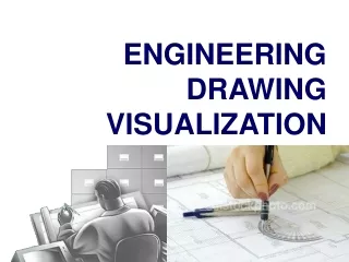
Graphic Language • engineer must have proficiency in • language, both written and oral, • Symbols associated with basic sciences • graphic language. Irrespective of language barriers, the drawings can be effectively used in other countries, in addition to the country where they are prepared. Thus, the engineering drawing is the universal language of all engineers.
Graphic Language • Importance of graphic language • Build new structures • Create new machines • Representing the existing ones. Without engineering drawing, it would have been impossible to produce objects An engineer should posses good knowledge, not only in preparing a correct drawing but also to read the drawing correctly.
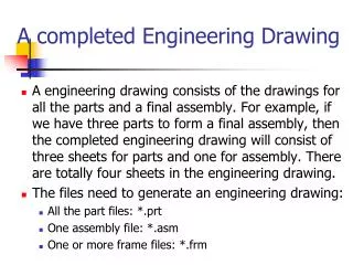
Classification of Drawing • Machine drawing
Classification of Drawing • Production drawing
Classification of Drawing • Part drawing
Classification of Drawing • Assembly drawing
Classification of Drawing • Detailed drawing
Classification of Drawing • Subassembly drawing
Classification of Drawing • Installation assembly drawing
Classification of Drawing • Installation for catalog drawing
Classification of Drawing • Assembly for instruction manual drawing
Classification of Drawing • Tabular Drawings
Classification of Drawing • Exploded assembly drawing
Classification of Drawing • Schematic assembly drawing
Classification of Drawing • Machine shop drawing
Classification of Drawing • Patent drawing
Chapter two Principle of Drawing
Drawing sheet -Sheet Size • Sheet size A5 A3 A4 A2 A1 A0 A4
Drawing sheet- Sheet Size • The basic principles involved in arriving at the sizes of drawing sheets are: • X : Y = 1 : • Example : A4 210:297 = 1:
Drawing sheet-Title block • The title block should lie within the drawing space • Containing the identification of the drawing • Location is at the bottom right hand corner.
Drawing sheet-Title block • The title block can have a maximum length of 170 mm. • providing the following information: • Title of the drawing • Sheet number • Scale • Symbol, denoting the method of projection • Name of the firm • Initials of staff drawn, checked and approved.
Drawing sheet-Title block PHAROS UNIVERSITY , FACULTY OF ENGINEERING 20 Power Screw 15 TITLE: DATE : 28/9/2013 SCALE: 1:2 10 Student ID # / SEC # ROLL NO: NAME: 10 instructor PLATE NO: EVALUATED BY 10 Exe Sheet # Example 001 75 110 To be used in all drawings
Drawing sheet-Title block 20 mm 100mm 10
Drawing sheet-Title block • SCALE 1 : 1 for full size, • SCALE × : 1 for enlarged scales, • SCALE 1 : × for reduced scales.
Drawing sheet-Line-application • Order of Priority of Coinciding Lines
Drawing sheet-Line-application • Order of Priority of Coinciding Lines
Drawing sheet-Line-application • Leader lines A leader is a line referring to a feature (dimension, object, outline, etc.). • Leader lines should terminate with : • with a dot, if they end within the outlines of an object • with an arrow head, if they end on the outline of an object • without dot or arrow head, if they end on a dimension line
Leader lines point to the corresponding part. Balloons containing part numbers.
The leader lines; • should not cross, • be as parallel as possible.
Examples of Sketches: Multiview Sketch
Examples of Sketches: Pictorial Sketch NOTE: There are also “technical sketches” used in industry which may include notes, and several versions that show motion.
Sketches use “proportion”, not scale! Proportion allows the designer to use approximate values to create a balanced looking object. Sketches are…accurate freehand drawings which use single lines to represent edges and features. Multi-line sketching is NOT used in engineering design. (Scribbling!)
Question! How do you know when a sketch or CAD drawing is complete? ANSWER: When the production people can make the part without having to ask you any questions! Most drawings not only have views of the object, but also we include written notes and dimensions to aid in its production.
Projection types: Drawings use various types of projection (how we view the object), to enhance our ability to visualize what we are being asked to see or understand. Let’s look at the various styles of projection used…