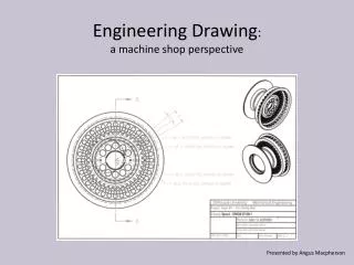
Comprehensive Guide to Creating and Annotating Engineering Drawings
This guide provides an in-depth overview of the process of creating engineering drawings, including individual parts and assemblies. It details the necessary files required, dimension annotation methods, dimension removal, arrow styling, and font adjustments. Additionally, it offers insights into managing multi-sheet drawings, including how to add new sheets and assembly files, as well as changing scales. With step-by-step instructions and essential parameters, it serves as a valuable resource for students and professionals in engineering design.

Comprehensive Guide to Creating and Annotating Engineering Drawings
E N D
Presentation Transcript
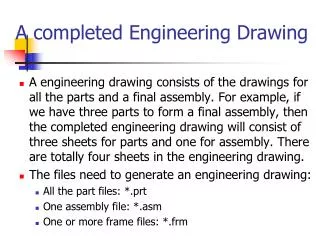
A completed Engineering Drawing • A engineering drawing consists of the drawings for all the parts and a final assembly. For example, if we have three parts to form a final assembly, then the completed engineering drawing will consist of three sheets for parts and one for assembly. There are totally four sheets in the engineering drawing. • The files need to generate an engineering drawing: • All the part files: *.prt • One assembly file: *.asm • One or more frame files: *.frm
Annotate 1 • How to show dimensions automatically on a drawing: • Annotate -> Show Model Annotations -> Select views, components, and/or features for which you want to show annotations -> V -> check on show -> Apply • How to delete dimensions on a drawing: • Select the dimensions you want to delete -> Delete
Annotate 2 • How to show dimensions on a drawing by hand: • Display a dimension between two points: Annotate -> |<->| -> select one point and the other -> move the cursor to the location you want to place the dimension and press down the middle mouse key • Display a diameter for a circle: Annotate -> |<->| -> double click on the circle, move the cursor to the location you want to place the dimension and press down the middle mouse key
Annotate 3 • How to show dimensions on a drawing by hand: • Display a dimension between two circle centers: Annotate -> |<->| -> click on one circle and the other -> Center -> Horizontal/Vertical -> OK • Display a radius for a circle: Annotate -> |<->| -> click once on the circle, move the cursor to the location you want to place the dimension and press down the middle mouse key
Annotate 4 • How to insert a jog: • Select a witness line by click on it -> press down the right mouse key -> Insert Jog -> Pick point on the witness line for the jog -> Select the position for the jog using mouse drag • How to remove a dimension: • Click on the dimension you want to remove -> press down Del key on keyboard
Annotate 5 • How to change arrow style: • File -> Drawing Options ->These options control leaders -> Option: draw_arrow_style; Value: filled, closed & open • How to change font: • File -> Drawing Options -> Active Drawing -> • drawing_text_height -> Option: draw_text_height; • Value: 0.08
Annotate 6 • How to show a text symbol: • Select the dimension you want to add text symbol -> Press down the right mouse key -> Properties -> Display -> move the cursor before @D -> Text Symbol -> select special symbol
Annotate 7 • Commonly-used values for the necessary parameters in a standard engineering drawing: • drawing_text_height: 3.5 (Active Drawing) • text_width_factor: 0.6 (Active Drawing) • projection_type: first_angle (These options control view and their annotations) • drawing_arrow_length: 3.5 (These options control leaders) • drawing_arrow_style: filled (These options control leaders) • drawing_arrow_width: 1.0 (These options control leaders) • drawing_arrow_style: filled (These options control leaders) • File -> Drawing Options -> change parameters -> Add/Change
Multi-Sheet Drawing 1 • Add a new drawing sheet: • Layout -> New Sheet • Check the page number and total number of pages • Add a new model in the new drawing sheet: • Layout -> Drawing Models or File -> Drawing Models -> Add Model -> select new model with preview option -> • Open -> Done
Multi-Sheet Drawing 2 • Create all the views: • General -> FRONT VIEW -> SIDE VIEW -> PLAN VIEW -> GENERAL VIEW • How to change scale: • Double click on the “view” -> Scale -> Custom scale -> • enter the proper scale you want -> Apply -> Close
Multi-Sheet Drawing 3 • Add an assembly file (*.asm): • Layout -> New Sheet -> Drawing Models or File -> Drawing Models -> Add Models -> select an *.asm file -> Open -> No combined state (without exploded)/ Default (with default exploded) • You may need to explode the assembly by hand as • we discussed in a previous class.
Announcement • Your homework assignments and midterm exam are due on Tuesday, Dec. 7, 2010. • I will post the final exam problems on Wednesday, Dec. 8, 2010 and collect your answers on Tuesday, Dec. 14, 2010, 10:30 PM at class room 237. This is a take-home exam. If you can finish it early, you may send me what I ask by E-mail. I will let you know if I receive all what I need via E-mail. • Finally, thank you and good luck to you all!