Avionics
AS MAN EVOLVED ... SO DID THE TECHNOLOGIES THAT HE USED. 2000s. 1940s. Evolution of. Avionics. Architecture. & Data Buses. Dr. J. SHANMUGAM MADRAS INSTITUTE OF TECHNOLOGY. AVIONICS. DEFINITION. Avionics : Avi ation Electr onics

Avionics
E N D
Presentation Transcript
AS MAN EVOLVED ... SO DID THE TECHNOLOGIES THAT HE USED 2000s 1940s Evolution of Avionics Architecture & Data Buses Dr. J. SHANMUGAM MADRAS INSTITUTE OF TECHNOLOGY
AVIONICS DEFINITION Avionics : Aviation Electronics Avionics : All electronic and electromechanical systems and subsystems (hardware and software) installed in an aircraft or attached to it. (MIL-1553A-HDBK) Avionics has become an equal partner and is surpassing aircraft structures and propulsion in terms of cost and its mission effectiveness of modern aircraft
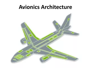
AVIONICS SYSTEM ARCHITECTURE • Establishing the basic architecture is the first and • the most fundamental challenge faced by the • designer • The architecture must conform to the overall aircraft • mission and design while ensuring that the avionics • system meets its performance requirements • These architectures rely on the data buses for intra • and intersystem communications • The optimum architecture can only be selected • after a series of exhaustive design tradeoffs that • address the evaluation factors
AVIONICS ARCHITECTURE • First Generation Architecture( 1940’s –1950’s) • Disjoint or Independent Architecture ( MiG-21) • Centralized Architecture (F-111) • Second Generation Architecture ( 1960’s –1970’s) • Federated Architecture (F-16 A/B) • Distributed Architecture (DAIS) • Hierarchical Architecture (F-16 C/D, EAP) • Third Generation Architecture (1980’s –1990’s) • Pave Pillar Architecture ( F-22) • Fourth Generation Architecture(Post 2005) • Pave Pace Architecture- JSF • Open System Architecture
FGA - DISJOINT ARCHITECTURE The early avionics systems were stand alone black boxes where each functional area had separate, dedicated sensors, processors and displays and the interconnect media is point to point wiring The system was integrated by the air-crew who had to look at various dials and displays connected to disjoint sensors correlate the data provided by them, apply error corrections, orchestrate the functions of the sensors and perform mode and failure management in addition to flying the aircraft This was feasible due to the simple nature of tasks to be performed and due to the availability of time
FGA - DISJOINT ARCHITECTURE Pilot Navigation Computer Radar Processor Navigation Panel Inertial Measurement Unit Altitude Sensor Display… Control Panel RF ….
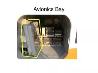
FGA - CENTRALIZED ARCHITECTURE • As the digital technology evolved,a central computer was added • to integrate the information from the sensors and subsystems • The central computing complex is connected to other • subsystems and sensors through analog,digital, synchro and • other interfaces • When interfacing with computer a variety of different transmission • methods , some of which required signal conversion (A/D) when • interfacing with computer • Signal conditioning and computation take place in one or more • computers in a LRU located in an avionics bay , with signals • transmitted over one way data bus • Data are transmitted from the systems to the central computer • and the DATA CONVERSION TAKES PLACE AT THE CENTRAL • COMPUTER
FGA - CENTRALIZED ARCHITECTURE ADVANTAGES • Simple Design • Software can be written easily • Computers are located in readily accessible bay DISADVANTAGES • Requirement of long data buses • Low flexibility in software • Increased vulnerability to change • Different conversion techniques needed at Central • Computer Motivated to develop a COMMON STANDARD INTERFACE for interfacing the different avionics systems.
FGA-CENTRALIZED ARCHITECTURE Tape GNC WDC HSI Multiplexer Converter HSD FCS Attack Radar Terrain Following Radar Inertial Navigator Set SMS Nav Data Display Panel RADALT Nav Data Entry Panel TACAN Doppler Radar Integrated Display Set Maintenance Control Unit
SGA– FEDERATED ARCHITECTURE • Federated : Join together, Become partners • Each system acts independently but united • (Loosely Coupled) • Unlike FGA – CA , Data conversion occurs at the system level and • the datas are send as digital form – called DigitalAvionics • Information Systems(DAIS) • Several standard data processors are often used to perform a • variety of Low – Bandwidth functions such as navigation, weapon • delivery , stores management and flight control • Systems are connected in a Time – Shared Multiplex Highway • Resource sharing occurs at the last link in the information chain – • via controls and displays • Programmability and versatility of the data processors
SGA– FEDERATED ARCHITECTURE • ADVANTAGES • Contrast to analog avionics – DDP provide precise solutions • over long range of flight , weapon and sensor conditions • Sharing of Resources • Use of TDMA saves hundreds of pounds of wiring • Standardization of protocol makes the interchangeability of • equipments easier • Allows Independent system design and optimization of • major systems • Changes in system software and hardware are easy to make • Fault containment – Failure is not propagated • DISADVANTAGES : Profligate of resources
Remote Terminal 1 Remote Terminal 2 Sensor Equipment Sensor Equipment SGA - DAIS HARDWARE ARCHITECTURE Processor1 Processor2 Processor M Bus Control Interface Bus Control Interface Bus Control Interface …… Data bus A Data bus B …… Remote Terminal N Control & Display Equipment
SGA - DISTRIBUTED ARCHITECTURE • It has multiple processors throughout the aircraft that are designed • for computing takes on a real-time basis as a function of mission • phase and/or system status • Processing is performed in the sensors and actuators ADVANTAGES • Fewer,Shorter buses • Faster program execution • Intrinsic Partitioning DISADVANTAGES • Potentially greater diversity in processor types • which aggravates software generation • and validation
SGA – HIERARCHICAL ARCHITECTURE • This architecture is derived from the federated architecture • It is based on the TREE Topology • ADVANTAGES • Critical functions are placed in a separate bus and Non-Critical • functions are placed in another bus • Failure in non – critical parts of networks do not generate • hazards to the critical parts of network • The communication between the subsystems of a particular • group are confined to their particular group • The overload of data in the main bus is reduced • Most of the military avionics flying today based on • HIERARCHICAL ARCHITECTURE
SGA- HIERARCHICAL SYSTEM EAP AVIONICS SYSTEM
TGA - WHY PAVE PILLAR • Pave Pillar is a USAF program to define the requirements and avionics architecture for fighter aircraft of the 1990s • The Program Emphasizes • Increased Information Fusion • Higher levels and complexity of software • Standardization for maintenance simplification • Lower costs • Backward and growth capability while making use of • emerging technology – VHSIC, Voice Recognition /synthesis • and Artificial Intelligence Contd…
TGA - WHY PAVE PILLAR • Provides capability for rapid flow of data in, through and from • the system as well as between and within the system • Higher levels of avionics integration and resource sharing of • sensor and computational capabilities • Pilot plays the role of a WEAPON SYSTEM MANAGER as • opposed to subsystem operator/information integrator • Able to sustain operations with minimal support, fly successful • mission day and night in any type of weather • Face a numerically and technologically advanced enemy • aircraft and defensive systems
TGA - PAVE PILLAR Higher Sustainability PP Lower LCC Mission Effectiveness
TGA – PAVE PILLAR ARCHITECTURE • Component reliability gains • Use of redundancy and resource sharing • Application of fault tolerance • Reduction of maintenance test and repair time • Increasing crew station automation • Enhancing stealth operation • Wide use of common modules (HW & SW)) • Ability to perform in-aircraft test and maintenance of avionics • Use of VHSIC technology and • Capability to operate over extended periods of time at austere, • deployed locations and be maintainable without the Avionics • Intermediate Shop
FTGA - WHY PAVE PACE • Modularity concepts cuts down the cost of the avionics related to • VMS, Mission Processing, PVI and SMS • The sensor costs accounts for 70% of the avionics cost • USAF initiated a study project to cut down the cost of sensors • used in the fighter aircraft • In 1990, Wright Laboratory – McDonnell Aircraft, Boeing aircraft • company and Lockheed launched the Pave Pace Program • Come with the Concept of Integrated Sensor System(IS2) • Pave Pace takes Pave Pillar as a base line standard • The integration concept extends to the skin of the aircraft – • Integration of the RF & EO sensors • Originally designed for Joint Strike Fighter (JSF)
KEY OBSERVATIONS AVIONICS ARCHITECTURAL EVOLUTION • Increased Digitization of Functions • Increased sharing and modularization of functions • Integration/ sharing concepts increased to the skin of the • aircraft • Functionality has increasingly obtained through software • Complex hardware architecture modules • Complex software modules • Increased network complexity and speed
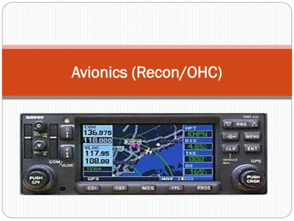
Data Bus • It provides a medium for the exchange of data and information between various Avionics subsystems • Integration of Avionics subsystems in military or civil aircraft and spacecraft.
Protocol • set of formal rules and conventions governing the flow of information among the systems • Low level protocols define the electrical and physical standards • High level protocols deal with the data formatting, including the syntax of messages and its format
TYPES OF PROTOCOLS Command/Response :Centralized Control Method Token Passing : Decentralized Control Method (Free token) CSMA/CA : Random Access Method
Topology How the systems are interconnected in a particular fashion LINEAR NETWORK Linear Cable All the systems are connected in across the Cable RING NETWORK Point to Point interconnection Datas flow through the next system from previous system SWITCHED NETWORK Similar to telephone network Provides communications paths between terminals
History of the MIL-STD-1553B • Developed at Wright Patterson Air Force • Base in 1970s • Published First Version 1553A in 1975 • Introduced in service on F-15 Programme • Published Second version 1553B in 1978
MILITARY STANDARD 1553 • MIL-STD-1553,Command / Response Aircraft Internal Time Division Multiplex Data Bus, is a Military standard (presently in revision B), which has become one of the basic tools being used today for integration of Avionics subsystems • This standard describes the method of communication and the electrical interface requirements for the subsystems connected in the data bus
Data Rate 1 Mbps 20 Bits Word Length Message Length 32 Word Strings(maximum) Data Bits per Word 16 Bits Transmission Technique Half - Duplex Encoding Manchester II Bi-phase Protocol Command Response Transmission Mode Voltage Mode SPECIFICATION OVERVIEW
ELEMENTS OF MIL-STD-1553B • BUS CONTROLLER (BC) • REMOTE TERMINAL (RT) • MONITORING TERMINAL (MT) • TRANSMISSION MEDIA
HISTORY & MOTIVATION • Single point failure in 1553B leads to certificability problem in civil aircraft • Addition of remote terminal requires changes in BC software which requires frequent certification • Standard adopted in the year 1977 • Made its appearance in the C-17 transport aircraft • Point to Point Protocol
ARINC SPECIFICATION 429 • It is a specification that defines a local area network for transfer of digital data between avionics system elements in civil aircraft. • It is simplex data bus using one transmitter but no more than twenty receivers for each bus implementation • There are no physical addressing. But the data are sent with proper identifier or label Contd…
ARINC 429 is viewed as a permanent as a broadcast or multicast operation • Two alternative data rates of 100kbps and 12-14 Kbps • There is no bus control in the data buses as found in MIL-STD 1553B • It has direct coupling of transmitter and receiving terminals
ARINC 429 ARCHITECTURE UPTO 20 RECEIVERS TOTAL ARINC429 DATABUS ARINC 429 TRANSMITTER ARINC 429 RECEIVER ARINC 429 RECEIVER ARINC 429 RECEIVER
BIRTH OF ARINC 629 1977 =>Boeing began to work on “DATAC” project 1977 - 85 =>DATAC Emerged as ARINC 629 1989 =>ARINC 629 was adopted by AEEC 1990 =>ARINC 629 was first implemented in BOEING-777
ARINC 629 DATA BUS Time Division Multiplex Linear Bus Multiple Transmitter Access 2 Mbps Data Rate Current Mode Coupling (Present implementation)
2 Mbps 20 Bits 31 Word Strings(maximum) 16 Bits Half - Duplex Manchester II Bi-phase Carrier Sense Multiple Access Collision avoidance Voltage Mode,Current Mode, Fiber Optic Mode SPECIFICATION OVERVIEW Data Rate Word Length Message Length Data Bits per Word Transmission Technique Encoding Protocol Transmission Mode
ARNIC 629 ARCHITECTURE UPTO 120 SUBSCRIBER TERMINALS ARINC 629 DATABUS ARINC 629 TERMINAL ARINC 629 TERMINAL ARINC 629 TERMINAL
Avionics Fully Duplex Switched Ethernet is an advanced Protocol Standard to interconnect avionics subsystems • It can accommodate future system • bandwidth demands • Increase flexibility in Avionics design • Reduce aircraft wire counts, thus • lowering aircraft weight and cost • Its first major use in A3xx
Since the Ethernet is a switched architecture rather than a point-point link, aircraft designers can create redundant sub networks • Faults can be isolated and analysed without impacting the system as a whole • ARINC 429 data bus may still be used but the main Avionics data pipe will be Ethernet (AFDX) of 100 Mbps
Used in F-22 Advanced tactical fighter • Generic version SAE Aerospace Standard 4074.1 • 50 Mbps- linear bus • for optical medium implementation – star topology • HSDB uses distributed control in which each terminal is permitted to transmit only when it receivesthe token frame.