Testing the Beam Interlock System
Testing the Beam Interlock System. 1. The Beam Interlock System Electrical and Physical Architecture Component Locations Design for Durability Scope of the Tests (CIBD and CIBU). 2. Power Supply Tests and Results Detailed Description of the Power Supply Test methods Test Results.

Testing the Beam Interlock System
E N D
Presentation Transcript
Testing the Beam Interlock System 1. The Beam Interlock System • Electrical and Physical Architecture • Component Locations • Design for Durability • Scope of the Tests (CIBD and CIBU) 2. Power Supply Tests and Results • Detailed Description of the Power Supply • Test methods • Test Results 3. User Interface Tests and Results • Detailed Description of the User Interface • Test methods • Test Results 3. Conclusions and Future Focus • Test Conclusions • Where do we go from here? Beam Interlock System
Testing the Beam Interlock System 1. The Beam Interlock System • Electrical and Physical Architecture • Component Locations • Design for Durability • Scope of the Tests (CIBD and CIBU) 2. Power Supply Tests and Results • Detailed Description of the Power Supply • Test methods • Test Results 3. User Interface Tests and Results • Detailed Description of the User Interface • Test methods • Test Results 3. Conclusions and Future Focus • Test Conclusions • Where do we go from here? Beam Interlock System
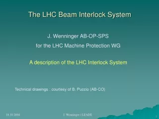
Beam Interlock System Locations Designed to protect CERN high energy accelerators = SPS / LHC / INJ / EXT Beam Interlock System
LHC Function BIS ~200 connections to User Systems distributed over 28kms Both-Beam LHC has 2 Beams Some User Systems give simultaneous permit Others give independent permit Beam-1 Beam-2 Beam Interlock System
Signals Beam Interlock System
Electrical Architecture USER SYSTEM rack “some radiation” Worst = UJ76-type In INTERLOCK rack “negligible radiation” Typical background at Sea Level 2U Chassis VMEChassis Beam Interlock System
Dependable Design • Critical Function separate (fewer critical circuits) • Failure Modes Analysis (weaknesses designed out) • Xilinx CPLD proven (AB/PO) • 5V and redundant PSU (Highly Available) • Mature Electronics (Not risky!) • Electro-Magnetic Compatibility (key issue from start) • = robust designreliability and rad tolerance seem linked! • -running ¼ LHC system in SPS for nearly 2 years Beam Interlock System
Motivations for the Tests The Beam Interlock Controller (x17 in LHC) -few in surface buildings -most in zones considered ‘negligible radiation’ -one in control room -VME Chassis can be moved to surface if ever there is a problem -any problem will result in safe failure by design VME is the basis = Not going to Test The User Interface (x130 in LHC) -Goes where the User System is “UJ76” We have to Test The User Interface Power Supply (x260 in LHC) -Goes where the User Interface is “UJ76” We have to Test -accumulated dose? User Systems will have the same problem! -need to know the limits -POWER SUPPLY only total dose is interesting Beam Interlock System
Typical Hardware User Interface BIC (Front) TT40 BIC (Rear) TT40 Beam Interlock System
Testing the Beam Interlock System 1. The Beam Interlock System • Electrical and Physical Architecture • Component Locations • Design for Durability • Scope of the Tests (CIBD and CIBU) 2. Power Supply Tests and Results • Detailed Description of the Power Supply • Test methods • Test Results 3. User Interface Tests and Results • Detailed Description of the User Interface • Test methods • Test Results 3. Conclusions and Future Focus • Test Conclusions • Where do we go from here? Beam Interlock System
CIBD Specification Tracopower TXL-025-25S 5V, 5A, 25W • Device housed in shielded conductive case • Reliability analysis = redundant PSU = good Availability • Decoupling diode added • +3% trim to accommodate Vdiode • 5A Fuse added on input • EMC Tests done with CIBU/CIBD configuration • Very good results • https://edms.cern.ch/document/762174/ • Not the cheapest, but • Tracopower have a great reputation (AB/PO) • Very complete datasheets Beam Interlock System
CIBD – 5A 5V PSU Beam Interlock System
CIBD – 5A 5V PSU ~12cm Beam Interlock System
CIBD – 5A 5V PSU PROSPERO 235U core and a 238U reflector “Displacement Damage Test” NEUTRONS Energy = 1MeV Fluence = 1E12 n/cm2 =Several 10’s Years LHC <1% Voltage change And CIBU OK down to 4.5V (guaranteed by design) PSU well protected - PSU 25W, we need <5W Degradation is expected & planned for Beam Interlock System
Testing the Beam Interlock System 1. The Beam Interlock System • Electrical and Physical Architecture • Component Locations • Design for Durability • Scope of the Tests (CIBD and CIBU) 2. Power Supply Tests and Results • Detailed Description of the Power Supply • Test methods • Test Results 3. User Interface Tests and Results • Detailed Description of the User Interface • Test methods • Test Results 3. Conclusions and Future Focus • Test Conclusions • Where do we go from here? Beam Interlock System
User Interface Specification Device housed in conductive case with Burndy Connectors -great EMC -good reliability from connectors (AB/PO already use these) Completely 5V -good reliability (more resistance to perturbation) Classic 7400 Series -mature technology -wide support Current Loop inputs -accommodate many different types of User System -DESY input circuit (M. Werner) RS485 Outputs -Good integrity -Mature Technology 9500 Xilinx CPLD for TEST and MONITOR -Manchester frames (Used General Machine Timing as a basis) -excellent dependability (AB/PO already use these) -Not susceptible to program corruption 100% remotely testable 100% remotely monitorable Beam Interlock System
User Interface Beam Interlock System
User Interface Specification Beam-2 Beam-1 Beam Interlock System
Test Areas Beam Interlock System
Test Areas Beam-2 Beam-1 Beam Interlock System
Test Areas Beam Interlock System
Test Areas Beam-2 Permit A Beam-1 Permit A Beam-2 Permit B Beam-1 Permit B Beam Interlock System
Test Areas All use the SAME electronic circuit! It’s repeated four times Beam-2 Permit A Beam-1 Permit A Beam-2 Permit B Beam-1 Permit B Beam Interlock System
USER PERMIT Paths The mission critical function for the CIBU; -relay USER_PERMITcorrectly Nothing else! All the BLACK lines are critical! Beam Interlock System
USER PERMIT Paths The mission critical function for the CIBU; -relay USER_PERMITcorrectly Beam Interlock System
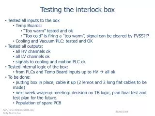
Test Sequence During Irradiation 5 steps, every two seconds we move to the next step, then repeat… We MEASURE all board current consumptions! PERMIT A [mA] … PERMIT B [mA] … CIBU [mA] Beam Interlock System
Test Sequence During Irradiation • 5 steps, every two seconds we move to the next step, then repeat… • Cycle USER PERMIT A Beam Interlock System
Test Sequence During Irradiation • 5 steps, every two seconds we move to the next step, then repeat… • Cycle USER PERMIT A • Cycle USER PERMIT B Beam Interlock System
Test Sequence During Irradiation • 5 steps, every two seconds we move to the next step, then repeat… • Cycle USER PERMIT A • Cycle USER PERMIT B • Cycle BEAM PERMIT INFO Beam Interlock System
Test Sequence During Irradiation • 5 steps, every two seconds we move to the next step, then repeat… • Cycle USER PERMIT A • Cycle USER PERMIT B • Cycle BEAM PERMIT INFO • Internal TEST PERMIT A Beam Interlock System
Test Sequence During Irradiation • 5 steps, every two seconds we move to the next step, then repeat… • Cycle USER PERMIT A • Cycle USER PERMIT B • Cycle BEAM PERMIT INFO • Internal TEST PERMIT A • Internal TEST PERMIT B Beam Interlock System
The Irradiated Zones • USER_PERMIT Optocoupler • USER PERMIT Current Regulation Circuit • USER PERMIT RS485 Driver • USER PERMIT Schmidt Trigger • The WHOLE CIBU Beam Interlock System
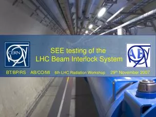
Irradiation Parameters Irradiation Parameters 60MeV Protons – OPTIS at PSI 15MeV/cm2/mg in SiO2 – can cause SEE in plastic packages N.B. 1 x 10¹¹protons cm-2 equivalent to 140 Gy “Representative of LHC Environment” – F. Faccio, M. Muhtinen Beam Interlock System
The Irradiated Zones Beam Interlock System
Test 1 – The Optocoupler Received a TOTAL DOSE of 62 Gy = 4.8 x 10¹⁰ pcm-2 10 Glitches observed – observation window open only ¼ of test - 40 assumed. Cross Section = 8.3 x 10⁻¹⁰for Optocoupler Glitches Beam Interlock System
Test 1 – The Optocoupler usual transition times were observed during the test ~3.6us delay for TRUE to FALSE ~0.6us delay for FALSE to TRUE Beam Interlock System
Test 2 – The Current Regulator Received a TOTAL DOSE of about 120 Gy NO Glitches observed Current regulation drifted by about 4% Beam Interlock System
Test 3 – RS485 Driver Received a TOTAL DOSE of 496 Gy NO Glitches observed, No FALSE Transistions FAILED SAFE at 496 Gy, power cycle restored operation Beam Interlock System
Test 4 – Schmidt Trigger Received a TOTAL DOSE of 1000 Gy (then experiment halted) NO Glitches observed, NO FALSE transitions Beam Interlock System
Test 5 – Whole PCB Two PCBs tested ~140-160Gy - CPLD stopped sending data frames Beam Interlock System
Overall Current Consumption Three PCBs tested at various points User Interface ID 1 = 180 Gy Beam Interlock System
Overall Current Consumption Three PCBs tested at various points User Interface ID 682 = 1650 Gy Beam Interlock System
Overall Current Consumption Three PCBs tested at various points User Interface ID 2 = 160 Gy Beam Interlock System
Testing the Beam Interlock System 1. The Beam Interlock System • Electrical and Physical Architecture • Component Locations • Design for Durability • Scope of the Tests (CIBD and CIBU) 2. Power Supply Tests and Results • Detailed Description of the Power Supply • Test methods • Test Results 3. User Interface Tests and Results • Detailed Description of the User Interface • Test methods • Test Results 3. Conclusions and Future Focus • Test Conclusions • Where do we go from here? Beam Interlock System
Conclusions • Critical Path of Beam Interlock System • - 8.3 x 10⁻¹⁰ Cross-Section for Glitches = use 1.6us GLITCH FILTER! • Good radiation tolerance • CPLD failed first at 150Gy – only for MONITORING • BUT once we got it back here – reprogrammed it and it worked! • Will monitor Glitch counters to indicate potential problems • Have plans for RAD HARD CIBU but they’re on hold • Needs motivation, time and money! ($) • VME is weak? move BICs to ‘surface’ ($$$) • Critical Matrix CPLD is same as in CIBU (3.3V variant) • VME PSU – redundant! • Have researched a RAD HARD BIC (not including VME) • Needs motivation, time and lots of money ($$$$$) Beam Interlock System
USER_PERMIT SEE Glitch Filter USER_PERMIT BEAM_PERMIT If USER_PERMIT FALSE for <=1.6us then it’s IGNORED! If USER_PERMIT FALSE for >1.6us then it’s ACCEPTED! = NO BEAM ABORT = BEAM ABORT Beam Interlock System
Closing remarks • -it was a LOT of effort to get the tests organised • -Thanks to Thijs Wijnands / Christophe Martin et al. for all the great work • -additional tests won’t need as much effort • afterLHC beam commissioning started – we could do some more! • If we feel it’s necessary: • Optical Transmission Board… (CIBO) • Fibre Extended User Interface (CIBFU/CIBFC) • VME Equipment (find the weaknesses?) • We should plan some beam time next year. NOT a priority for LHC • “Better the devil you know” Beam Interlock System
FIN Beam Interlock System
Tracopower TXL-025-25S INPUT VOLTAGE fails or glitches = OUTPUT VOLTAGE maintained Mean Time Between Failures = several years Industrial Device = heavily tested, good conformity Short Circuit and Over Voltage Protected Three Year Guarantee Beam Interlock System