Basics of the Beam Interlock System
290 likes | 413 Vues
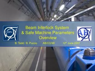
The Beam Interlock System (BIS) oversees safety for LHC experiments with 200 user systems spread across 28 km. It supports two beams and allows for simultaneous or independent permits, ensuring high-speed and dependable operations. Key features include hardwired user systems, redundancy in connections, and safe beam flag controls. The architecture incorporates designated racks near experiments for integration. Parameters for safe machine operations and interlocks are meticulously managed to ensure safety and efficiency in physics experimentation.

Basics of the Beam Interlock System
E N D
Presentation Transcript
Basics of the Beam Interlock System BIS ~200 User Systems distributed over 28kms Both-Beam LHC has 2 Beams Some User Systems give simultaneous permit Others give independent permit Beam-1 Beam-2 System is HIGH SPEED, HIGHLY DEPENDABLE (SIL 3) LHC Beam Interlock System
Layout Beam Interlock System forms a transparent layer from User System to Beam Dump LHC Beam Interlock System
Signals LHC Beam Interlock System
Signals LHC Beam Interlock System
Signals BEAM_PERMIT_STATUS is now called BEAM_PERMIT_INFO LHC Beam Interlock System
Electrical Architecture In USER rack Cable In INTERLOCK rack User System 2U Chassis VME Chassis LHC Beam Interlock System
Key Features Concerning the USER • User Systems can be Maskable or Unmaskable • This is hardwired • Safe Beam Flag controls the mask at the controller • experimentsareunmaskable <= Heavy influence on commissioning! • 2.redundant Links are required • For every interlock • test mode needed which can check this redundancy • https://edms.cern.ch/file/636589/1.4/CIBU-User-Manual-1v4.pdf • Describes Interface to CIBU… • - two power supplies, needs two 220V sockets LHC Beam Interlock System
Experiment Connections • A Rack has been designated near each experiment to help integration to the Beam Interlock System and Safe Machine Parameters User Permits Beam Interlock System Experiment Machine Controls Rack Timing System Safe Machine Parameters Rack numbers: 4Y.02-03.A1 : US15 C28 : RB26 S1E08 : USC55 7Y-D3B09 : UX85 LHC Beam Interlock System
Experiment Connections • Rack can contain User Interface (Alice) or Patch Panel (CMS) or both! User Permits Beam Interlock System Experiment Machine Controls Rack Cable installation is managed by AB/CO Cable Installation is managed by Experiment Patch-panels with Burndy connectors are provided by AB/CO LHC Beam Interlock System
Safe Machine Parameters… LHC Beam Interlock System
What are the Parameters LHC Beam Interlock System
Distribution LHC BIS SPS Extraction BIS (TI8 / TI2) Management Critical Settings EI_th, Imin_th E_physics, E_injection deltaE, Emax, SqueezeMap LHC Sequencer (LSA) Mode & Squeeze Currents LBDS Beam Dump syst. Beam_Permit1 & 2 CTG Master Timing Generator CTRV CTRV Events, UTC, & Telegrams ( including Safe Machine Parameters) Timing Network Energy @10Hz SBF1 & 2 Energy 1 I_beam1 & 2 BEM @1kHz CTRV Safe Machine Parameter System BEM/BCT interface CTRV BEM User_Permits Energy 2 I_beam1 & 2 BCT-DC Injection kickers BLM Aperture Kickers Experiments Collimators CTRV CTRV CTRV CTRV CTRV BCT-FR CTRV BPF1 & 2 (1 kHz) LHC Beam Interlock System
GMT CRATE Concerning the GMT connections The “Machine Controls” rack hosts the GMT system for delivering the Flags: Directly from the CTRV board (TTL signal => short distance) or via a Cable Driver card. Machine Controls rack Supplied, installed, managedand maintained by AB/CO connection from GMT network (LHC Timing ) short distance « System A» requiring Flags CTRV « System B» requiring Flags CTD (cable driver) Supply and Installation of these cables are managed by the Experiments LHC Beam Interlock System
Issue concerning the GMT system installation The GMT system can either be VME or PC based depending on the number of triggers, fanout and space available in the dedicated rack. Nobody (except LHCb) has replied to our request (meeting of May 14th)! • We must know soon for the points 1,2 and 5: • How many systems are going to use the Flags? • How far are they from the rack? • (Except CO systems) which system is going to be also present in the rack? Consequently what is the space available in the rack? LHC Beam Interlock System
Fin… LHC Beam Interlock System
CIBUD CIBUS The CABLES between EXP and the Rack (when the CIBU is NOT installed in the Machine Controls rack) • In all cases: cable type is NE12 FIN • for Both-beam connection: a 12-pin male Burndy is required at each end Machine rack 12-pin male • for the Beam-1 connection: a 12-pin male Burndy is required at each end • for the Beam-2 connection: a 12-pin female Burndy is required at each end Machine rack 12-pin male 12-pin female • For EMC Compatibility and Signal Integrity: a cabling convention MUST be followed => see dedicated document on the cable assembly procedure: https://edms.cern.ch/document/766261/1.0 LHC Beam Interlock System
Point 1 CIBUD CIBUS CIBUS CIBUS Rack 4Y.02-03.A1 (in USA 151) ATLAS_DETECTOR User_Permit for both beam BIC “R1” (in US152) Unmaskable ATLAS_MOVABLE_DEVICES User_Permit for Beam1 User_Permit for Beam2 Unmaskable Unmaskable Maskable ATLAS_EXPERIMENT_MAGNET User_Permit for both beam Unmaskable LHCf_DETECTOR User_Permit for both beam Rack Y.26-05.A1 or Y.26-05.A1 LHC Beam Interlock System
Point 2 CIBUS CIBUS Rack in UX25/C28 ALICE_DETECTOR User_Permit for both beam BIC “R2” (in UA27) Unmaskable ALICE_EXPERIMENT_MAGNETS User_Permit for both beam Maskable BIC “INJ1” (in SR2) Unmaskable ALICE_ZDC_Beam12 User_Permit for Inj-Beam1 (ZDC electronic rack in UA23) LHC Beam Interlock System
Point 5 CIBUD CIBUS CIBUS CIBUS TOTEM_DETECTOR User_Permit for both beam Rack S1E08 (in USC55) TOTEM_MOVABLE_DEVICES User_Permit for Beam1 User_Permit for Beam2 BIC “R5” (in UJ56) Unmaskable Unmaskable Unmaskable CMS_DETECTOR User_Permit for both beam Unmaskable Maskable CMS_EXPERIMENT_MAGNET User_Permit for both beam LHC Beam Interlock System
Point 8 CIBUS CIBUS CIBUS Rack 7Y-D3B09 (in UX85) LCHb_DETECTOR User_Permit for both beam BIC “R8” (in UA87) Unmaskable LHCb-VELO_Beam12 User_Permit for both beam Unmaskable Maskable LHCb_EXPERIMENT_MAGNET User_Permit for both beam LHC Beam Interlock System
Typical Hardware User Interface BIC (Front) TT40 BIC (Rear) TT40 LHC Beam Interlock System
Testing with ‘A’ and ‘B’ LHC Beam Interlock System
Testing with ‘A’ and ‘B’ LHC Beam Interlock System
Testing with ‘A’ and ‘B’ User System to User Interface TEST in the same way LHC Beam Interlock System
Beam Permit Loops & BICs Beam Dump Beam-1andBeam-2 4 fibre-optic channels from Point 6 1 clockwise & 1 anticlockwise for each Beam • 10MHz Square wave generated at IP6 • Signal can be cutby any Controller • Signal can be monitoredby any Controller When any of the four 10MHz signals are absent at IP6, BEAM DUMP! Beam-1 / Beam-2 areIndependent! Beam Interlock Controllers (BIC) 16 BICs per beam - Two at each Insertion Point Up to 20User Systems per BIC 6 x Beam-1 8 x Both-Beam 6 x Beam-2 LHC Beam Interlock System
Beam Interlock System Locations Designed to protect CERN high energy accelerators = SPS / LHC / INJ / EXT LHC Beam Interlock System
Layout In LHC, BIS forms a transparent layer from User System to Beam Dump LHC Beam Interlock System
Layout In LHC, BIS forms a transparent layer from User System to Beam Dump LHC Beam Interlock System