Download
1 / 15
150 likes | 337 Vues
Effective Color Interpolation in CCD Color Filter Arrays Using Signal Correlation. 作者 : Soo -Chang Pei , Io- Kuong Tam 出處 : IEEE TRANSACTIONS ON CIRCUITS AND SYSTEMS FOR VIDEO TECHNOLOGY, VOL. 13, NO. 6, JUNE 2003 報告人 : 董文豪 日期 :2011/05/04. Outline. Introduction

E N D
Effective Color Interpolation in CCD Color Filter Arrays Using Signal Correlation 作者:Soo-Chang Pei,Io-Kuong Tam 出處: IEEE TRANSACTIONS ON CIRCUITS AND SYSTEMS FOR VIDEO TECHNOLOGY, VOL. 13, NO. 6, JUNE 2003 報告人:董文豪 日期:2011/05/04
Outline • Introduction • Color Filter Arrays (CFA) • Conventional interpolation methods • Bilinear • Edge-sensing interpolation • Proposed interpolation method • Experiment results
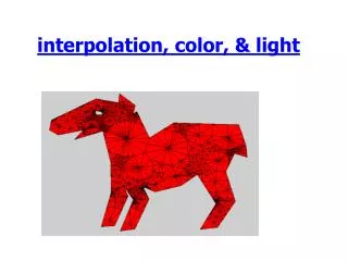
Introduction • The authors propose an effective color filter array (CFA) interpolation method for digital still cameras using a simple image model that correlates the R,G,B channels. • A low-complexity interpolation method to improve the image quality.
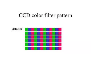
Color Filter Arrays -CFA ( 1/2 ) Three-CCD structure for a DSC. Single-CCD structure for a DSC.
Conventional interpolation methods ( 1/4 ) • Bilinear G3+G6+G8+G11 4 G’7= R1 B2 G3 B4 R1+R7 2 R’3= R5 G6 R7 G8 R9 B10 G11 B12 B2+B4+B10+B12 4 B’7= R13
Conventional interpolation methods ( 2/4 ) • Bilinear H H L L H H L L H H L L H H L L Vertical edge patterns An obvious error is produced and the edge pattern is destroyed.
Conventional interpolation methods ( 3/4 ) • Edge-sensing interpolation ( G ) R1 G6 + G8 2 G’7H= ∆H=|G6 - G8| , ∆V=|G3 – G11|, If ( ∆H < T ) and ( ∆V > T ) , G’7 = G’7H , else if ( ∆V < T ) and ( ∆H > T ) , G’7 = G’7V else G’7 = G’7A B2 G3 B4 G3 + G11 2 G’7V= R5 G6 R7 G8 R9 B10 G11 B12 G3 + G6 + G8 + G11 4 G’7A= R13
Conventional interpolation methods ( 4/4 ) • Edge-sensing interpolation ( R,B ) R1 B G R G HB = , HR= B2 G3 B4 B 2 G’2 B 4 G’4 G3 2 ( + ) /2 B’3 = ( ) R5 G6 R7 G8 R9 B 2 G’2 B 4 G’4 B10 G’10 B 12 G’12 G’7 4 B10 G11 B12 B’7= ( + ++ ) /4 ( ) R13
Proposed interpolation method ( 1/3 ) • Above two methods use only the existing G channel neighborhood information to find the missing G values. • There is a high correlation between the R,G,B channels. • The G channel can take advantage of the R and B information.
Proposed interpolation method ( 2/3 ) G channel image KR channel image KB channel image KR = G – R KB = G – B
Proposed interpolation method ( 3/3 ) R,B Channel Interpolation G Channel Interpolation R1 +( K’R3 + K’R6 + K’R8 + K’R11 ) /4 G’7 = R7 1 4 1 2 1 2 = R7 + [G3 - (R7+R1) + G6 - (R7+R5) + G8 - (R7+R9) + G11- (R7+R13)] R’3 = G3 - ( K’R1 + K’R7 ) B2 G3 B4 1 2 R5 G6 R7 G8 R9 1 2 1 4 B’7= G’7- ( K’B2+ K’B4+ K’B10+ K’B12 ) 1 2 B10 G11 B12 1 4 1 2 = R7+ ( G3+G6+G8+G11 ) - ( R1+R5+R9+R13 ) R13 1 8 KR = G – R KB = G – B
Experiment results ( 1/2 ) PSNR OF THE INTERPOLATED RESULTS
Experiment results ( 2/2 ) COMPLEXITY COMPARISON 1 4 1 2 G’7 = R7+ ( G3+G6+G8+G11 ) - ( R1+R5+R9+R13 ) 1 8