Download
1 / 23
230 likes | 408 Vues
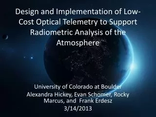
Design and Implementation of Low-Cost Optical Telemetry to Support Radiometric Analysis of the Atmosphere. University of Colorado at Boulder Alexandra Hickey, Evan Schomer , Rocky Marcus, and Frank Erdesz 3/14/2013. Mission Overview. Mini Cam Subsystem on Polar Cube Low Cost

E N D
Design and Implementation of Low-Cost Optical Telemetry to Support Radiometric Analysis of the Atmosphere University of Colorado at Boulder Alexandra Hickey, Evan Schomer, Rocky Marcus, and Frank Erdesz 3/14/2013
Mission Overview • Mini Cam Subsystem on Polar Cube • Low Cost • Data confirmation • Through goe tagging • Contextual image comparison • Provides simplified means for post launch recalibration
Design overview • Three Subsystems • Structures • CDH • Power • Goal • Compact • Easy to interface • Durable
This Semester • Worked toward balloon launch • Not met due to technical difficulties that will be talked about later by the different subsystems
Requirements/Overview • fit with in a 1.4in x 1.2in x 1.14in volume • Weigh under 200g • Easily integrate into Polar Cube • Withstand at least 20g’s with a factor of safety of two • Maintain all components within operating temperatures
The Design • PCB structural members • Stand offs • Nylon washers • Prevent moment about the stand offs • Reinforced holes for stand offs
Overview/Requirements • CDH is handled with an AVR ATmega1284P microcontroller. • CDH shall be able to handle image data streaming up 1Mbps from the image sensoras well as interfacing with memory and temperature sensors. • CDH shall write any event or peripheral settings data to nv memory. • CDH shall be able to locally store all data for an extended period. • CDH shall be able to function as a satellite subsystem or standalone system.
Microcontroller and Peripherals Microcontroller ATmega1284P Memory Interface SPI NV Memory OneWire Interface JPEG Data Stream 8-bit parallel Temperature Sensors (x3) Camera Module Aptina MT9T111 Command Interface I2C
Image Capture Flow Picture Trigger • Check memory requirements • Prep buffer • Find address location of nv memory • Create image entry/start headers • Set camera settings if necessary • Gather timestamp and other data Send Camera Capture Command Receive camera data and store into vram buffer Check Camera EOF Load buffer into non-volatile memory • Finish EOF headers on nv memory • Set low power mode on camera/memory • Increment photo ID • Add flight log data (time,settings,name) Return
Data Storage Images with a maximum size of 1.0 MB per photo at full color resolution will be collected. The camera may cycle through various modes affecting data output size up to 1.0 MB throughout the mission. With a 256MB memory module, up to 254 images and supporting mission log data can be stored locally until uploaded to the main computer memory allowing for a data transfer to be postponed for an extended period.
Learned • Processor bus read optimization for large data transfers. • Find sufficient documentation for camera before purchasing. • Interfacing with a complex and micro sized camera system and changing various settings through a command interface.
Power Subsystem Requirements • Will provide 5V to the microcontroller. • Will use 3.3V from PolarCube to power the voltage regulator, DC-DC converter, and memory module. • Will provide 2.8V and 1.8V to the camera module.
Schematics Voltage Regulation
Lessons Learned • Improvements on PCB design process • Learned more circuit debugging strategies
Conclusion • Will provide a contextual image for geo tagging and general data confirmation • Allows for easier resolution of anomalous readings • Lowers overall Polar Cube mission risk