CHAPTER 1 INTRODUCTORY DIGITAL CONCEPTS
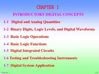
CHAPTER 1 INTRODUCTORY DIGITAL CONCEPTS. 1-1 Digital and Analog Quantities. 1-2 Binary Digits, Logic Levels, and Digital Waveforms. 1-3 Basic Logic Operations. 1-4 Basic Logic Functions. 1-5 Digital Integrated Circuits. 1-6 Testing and Troubleshooting Instruments.

CHAPTER 1 INTRODUCTORY DIGITAL CONCEPTS
E N D
Presentation Transcript
CHAPTER 1 INTRODUCTORY DIGITAL CONCEPTS 1-1Digital and Analog Quantities 1-2Binary Digits, Logic Levels, and Digital Waveforms 1-3Basic Logic Operations 1-4Basic Logic Functions 1-5Digital Integrated Circuits 1-6Testing and Troubleshooting Instruments 1-7Digital System Application Chapter 1
CHAPTER OBJECTIVES • Explain the basic differences between digital and analog quantities • Show how voltage levels are used to represent digital quantities • Describe various parameters of a pulse waveform such as rise time, fall time, pulse width, frequency, period, and duty cycle • Explain the basic logic operations of NOT, AND, and OR • Describe the basic functions of the comparator, adder, code converter, encoder, decoder, multiplexer, demultiplexer, counter, and register • Identify digital integrated circuits according to their complexity and the type of circuit packaging • Identifypin numbers on integrated circuit packages Chapter 1
CHAPTER OVERVIEW For many years, applications of digital electronics were confined to computer systems. Today, digital technology is applied in a wide range of areas. Such applications as television, communications systems, radar, navigation and guidance systems, military systems, medical instrumentation, industrial process control, andconsumer electronicsuse digital techniques. Digital technology has progressed fromvacuum-tube circuitstodiscrete transistors to complex integrated circuits, some of which contain millions of transistors. Chapter 1
1-1Digital and Analog Quantities After completing this section, you should be able to • Define digital • Define analog • Explain the difference between digital and analog quantities • State the advantages of digital over analog • Give examples of how digital and analog quantities are used in electronics Chapter 1
Temperature (℉) 100 95 90 85 80 75 70 Time of day A.M. P.M. 1 1 2 2 3 3 4 4 5 5 6 6 7 7 8 8 9 9 10 10 11 11 12 12 Electronic circuits can be divided into two broad categories Analog electronic circuit It involves Analogquantities Having continuous values. example: time, pressure, distance, sound Chapter 1
Temperature(℉) 100 95 90 85 80 75 70 Time of day 1 2 3 4 5 6 7 8 9 10 11 12 1 2 3 4 5 6 7 8 9 10 11 12 A.M. P.M. Digital electronic circuit It involves digital quantities Having a discrete set values It is important to realize that itself is not the digital representation of the analog quantity. Chapter 1
The Digital Advantage 1. digital data can be processed and transmitted more efficiently and reliably than analog data. 2.digital data has a great advantage when storage is necessary. For example, music when converted to digital form can be stored more compactly and reproduced with greater accuracy and clarity than is possible when it is in analog form 3.Noise (unwanted voltage fluctuations) does not affect digital data nearly as much as it does analog signals. Chapter 1
Original sound waves Amplified audio signal Microphone Reproduced sound waves Speaker Audio signal Linear amplifier An analog electronic system A public address system Chapter 1
CD driver sound waves Linear amplifier Digital-to-analog converter Digital data Analog reproduction of music audio signal Speaker A system using digital and analog methods A compact disk (CD) player Chapter 1
1-2Binary Digits, Logic Levels, and Digital Waveforms After completing this section, you should be able to • Define binary • Define bit • Name the bits in a binary system • Explain how voltage levels are used to represent bits • Explain how voltage levels are interpreted by a digital circuit • Describe the general characteristics of a pulse • Determine the amplitude, risetime, falltime, and width of a pulse • Identify and describe the characteristics of a digital waveform • Determine the amplitude, period, frequency, and duty cycle of a digital waveform • Explain what a timing diagram is and state its purpose • Explain serial and parallel data transfer and state the advantage and disadvantage of each Chapter 1
There are only two possible states in digital electronics circuits and systems. These states are represented by two different voltage levels: A HIGH and a LOW. The two states can also be represented by current levels, open and closed switches, or lamps turned on and off. The two-state number system is called binary, and its two digits are 0 and 1. A binary digit is called a bit. Chapter 1
Binary digits The two digits in the binary system, 1 and 0, are called bits, which is a contraction of the words binary digit. In digital circuits, two different voltage levels are used to represent the two bits. Positive logic: HIGH = 1 and LOW = 0 Negative logic: HIGH = 0 and LOW = 1 In digital systems, combinations of the two states, called codes, are used to represent numbers, symbols, alphabetic characters, and other types of information. Chapter 1
TTL 5V 2V VH(max) 0.8V HIGH (binary1) VH(min) 0V unacceptable VL(max) LOW (binary0) VL(min) 2. Logic Levels The voltages used to represent a 1 and a 0 are called logic levels. Ideally, one voltage level represents a HIGH and another voltage level represents a LOW. Chapter 1
u t t u u t 3. Digital Waveforms 脉冲信号 Chapter 1
falling edge falling edge Leading edge Leading edge trailing edge Leading edge A digital waveform is made up of a series of pulses. (1) The pulse (ideal pulse) Rising edge Rising edge Positive-going pulse negative-going pulse 3V 3V (0V) (0V) 0V (-3V) 0V (-3V) Chapter 1
0.9 A 0.5 A tw Amplitude tf tr 0.1 A Nonideal pulse Rise time Pulse width Fall time Chapter 1
T1 T2 T3 T4 T5 (2)Waveform Characteristics Most waveforms encountered in digital systems are composed of series of pulses, sometimes called pulse trains, and can be classified as either periodic or nonperiodic. A periodic pulse waveform is one that repeats itself at a fixed interval, called period( T ). A frequency( f ) is the rate at which it repeats itself and is measured in hertz(Hz). Chapter 1
T1 T2 T3 T4 T5 Periodic(square wave) An important characteristic of a periodic digital waveform is its duty cycle. The ratio of the pulse width(tw) to the period(T) duty cycle: Chapter 1
Nonperiodic A nonperiodic pulse waveform, of course, does not repeat itself at fixed intervals and may be composed of pulses of randomly differing pulse widths and/or randomly differing time intervals between the pulse. Chapter 1
Bit time Clock A 4.A Digital Waveform Carries Binary Information Binary information that is handled by digital systems appears as waveforms that represent sequences of bits. Each bit in a sequence occupies a defined time interval called a bit time. The Clock In digital systems, all waveforms are synchronized with a basic timing waveform called the clock. The clock is a periodic waveform in which each interval between pulses (the period) equals the time for one bit. 1 0 0 1 Chapter 1
Clock 1 2 3 4 5 6 8 7 A B C 5. Timing Diagrams A timing diagram is a graph of digital waveforms showing the actual time relationship of two or more waveforms and how each waveform changes in relation to the others. a. Determine the states (HIGH or LOW) of all the waveforms at any specified point in time b. Determine the exact time that a waveform changes state relative to the other waveforms. Chapter 1
Modem Computer 6. Data Transfer Data refers to groups of bits that convey some type of information. In computer systems, binary data are transferred in two ways: serial and parallel. (1) Serial transfer send one bit at a time along a single conductor 1 0 1 1 0 0 1 0 t0t1t2t3t4t5t6t7 Advantage: only one line is required. Disadvantage: it takes longer to transfer a given number of bits than with parallel transfer. Chapter 1
1 0 1 1 0 0 1 0 Printer Computer t0 t1 (2) parallel transfer send bits on separate lines at the same time. Advantage: It can transfer data at one time. Disadvantage: it takes more lines. Chapter 1
1-3BASIC LOGIC OPERATION After completing this section, you should be able to • List three basic logic operations • Define the NOT operation • Define the AND operation • Define the OR operation The term logic is applied to digital circuits used to implement logic functions. Several kinds of digital logic circuits are the basic elements that form the building blocks for such complex digital systems as the computer. Chapter 1
R E F A Three basic logic operations: (1) NOT The NOT operation changes one logic level to the opposite logic level. 1 0 0 1 Symbol: The NOT operation is implemented by a logic circuit known as an inverter. Chapter 1
1 1 0 1 1 0 0 0 0 1 0 0 C A B F E (2) AND When one input is HIGH and the other input is HIGH, the output is HIGH. When any or all inputs are LOW, the output is LOW. Symbol: The AND operation is implemented by a logic circuit known as an ANDgate. Chapter 1
A B 1 0 0 1 0 0 1 1 1 1 0 1 C F E (3) OR When one input is HIGH or the other input is HIGH or both inputs are HIGH, the output is HIGH. When both inputs are LOW, the output is LOW. Symbol: The OR operation is implemented by a logic circuit known as an OR gate. Chapter 1
1-4BASIC LOGIC FUNCTION After completing this section, you should be able to • Identify eight basic types of logic functions • Describe a basic magnitude comparator • List the four arithmetic functions • Describe a basic adder • Describe a basic encoder • Describe a basic decoder • Define multiplexing and demultiplexing • State how data storage is accomplished • Describe the function of a basic counter Chapter 1
Comparator A>B A=B A<B A B Two binary numbers Outputs Basic magnitude comparator • The Comparison Function Magnitude comparison is performed by a logic circuit called a comparator. Chapter 1
Comparator A>B A=B A<B A B Example: A less than B(2<5) as indicated by HIGH output(A<B) LOW LOW HIGH Binary code for 2 Binary code for 5 Chapter 1
Adder A B Cin Σ Cout Two binary numbers Basic adder 2. The Arithmetic Functions (1) Addition Addition is performed by a logic circuit called an adder. Sum Carry out Carry in Chapter 1
Adder A B Cin Σ Cout Example:A plus B (3+9=12) Binary code for 3 Binary code for 2 Binary code for 9 Binary 1 Binary 0 Binary code for 12 Chapter 1
(2) Subtraction A subtracter requires three inputs: the two numbers that are to be subtracted and a borrow input. The two outputs are the difference and the borrow output. The subtraction can actually be performed by an adder because subtraction is simply a special case of addition. (3) Multiplication Multiplication is performed by a digital circuit called a multiplier. Two inputs are required. The output of the multiplier is the product. Because multiplication is simply a series of additions with shifts in the positions of the partial products, it can be performed by using an adder in conjunction with other circuits. Chapter 1
(4) Division Two inputs to the divider are required, and the outputs generated are the quotient and the remainder. Division can be performed with a series of subtractions, comparisons, and shifts, and thus it can also be done using an adder in conjunction with other circuits. 3. The Code Conversion Function A code is a set of bits arranged in a unique pattern and used to represent specified information. A code converter changes one form of coded information into another coded form. Chapter 1
HIGH encoder 9 8 7 6 5 4 3 2 1 0 7 8 9 4 5 6 1 2 3 0 . +/- Calculator keypad 4. The Encoding Function The encoding function is performed by a logic circuit called an encoder. The encoder converts information into some coded form. Binary code for 9 9 Chapter 1
Decoder 7-segment display 5. The Decoding Function The decoding function is performed by a logic circuit called a decoder. The decoder converts coded information into a noncoded form. Binary input Chapter 1
6. The Data Selection Function Two types of circuits that select data are the multiplexer and the demultiplexer. The multiplexer, (mux), is a logic circuit that switches digital data from several input lines onto a single output line in a specified time sequence. The demultiplexer (demux) is a logic circuit that switches digital data from one input line to several output lines in a specified time sequence. The demux is a mux in reverse. Chapter 1
7. The Storage Function Storage is a function that is required in most digital systems. Common types of storage devices are flip- flops, registers, semiconductor memories, magnetic disks, magnetic tape, and optical disks (CDs). (1) flip-flops The flip-flop is a bistable (two stable states) logic circuit that can store only one bit at a time, either a 1 or a 0. The output of a flip-flop indicates which bit it is storing. A HIGH output indicates that a 1 is stored and a LOW output indicates that a 0 is stored. Flip-flops are implemented with logic gates. Chapter 1
0 0 0 0 0 1 1 0 0 0 0 0 1 0 1 0 1 0 0 0 0101 010 01 0 0 1 0 0 1 0 1 0 (2) Registers A register is formed by combining several flip-flops so that groups of bits can be stored. The two basic types of shift registers are serial and parallel. serial shift register Parallel shift register 0 1 0 1 Chapter 1
(3) Semiconductor Memories Semiconductor memories are devices typically used for storing large numbers of bits. Types of memory: the read-only memory (ROM), the random-access memory (RAM). (4) Magnetic Memories Magnetic disk memories are used for mass storage of binary data. Examples: floppy disks , the computer's internal hard disk, magnetic tape Chapter 1
Counter Input pulses 8. The Counting Function There are many types of digital counters, but their basic purpose is to count events represented by changing levels or pulses or to generate a particular code sequence. Storage capability is an important characteristic of all counters, and flip-flops are generally used to implement them. Binary codes which represent the number of input pulse counted Chapter 1
1-5DIGITAL INTEGRATED CIRCUIT After completing this section, you should be able to • Recognize the difference between through-hole devices and surface-mount devices • Identify dual-in-line packages (DIP) • Identify small-outline integrated circuit packages (SOIC) • Identify plastic leaded chip carrier packages (PLCC) • Identify leadless ceramic chip carrier packages (LCCC) • Identify flat packs (FP) • Determine pin numbers on various types of IC packages • Explain the circuit complexity classifications of integrated circuits Chapter 1
Modem digital systems use ICs almost exclusively in their designs because of their small size, high reliability, low cost, and low power consumption. A monolithic integrated circuit (IC) is an electronic circuit that is constructed entirely on a single small chip of silicon. Chapter 1
1. IC Packages Integrated circuit (IC) packages are classified according to the way they are mounted on printed circuit boards (PCB) as either through-hole mounted or surface mounted. (1) through-hole type packages Pins are inserted through holes in the PCB and can be soldered to conductors on the opposite side. Example: the dual-in-line package (DIP) Chapter 1
(2) surface-mounted packages The holes through the PCB are unnecessary. The pins of surface-mounted packages are soldered directly to conductors on one side of the board, leaving the other side free for additional circuits. Surface mounting is a newer, space-saving alternative to through-hole mounting. Chapter 1
Example: the small-outline integrated circuit (SOIC) , the PLCC (plastic leaded chip carrier), the LCCC (leadless ceramic chip carrier), the flat pack (FP), the SSOP (shrink small-outline package), the TSSOP (thin shrink small-outline package), and the TVSOP (thin very small-outline package). Chapter 1
Pin 1 identifier Notch Pin 1 identifier DIP or SOIC PLCC or LCCC 2. Pin Numbering 1 2 3 4 5 6 7 8 16 15 14 13 12 11 10 9 3 2 1 19 18 14 4 5 6 7 8 9 13 Chapter 1
3. Integrated Circuit Complexity Classifications Integrated circuits are classified according to their complexity. (1) Small-scale integration (SSI) Integrated circuits that have up to twelve equivalent gate circuits on a single chip. Example: basic gates and flip-flops. (2) Medium-scale integration (MSI) Integrated circuits that have from 12 to 99equivalent gates on a chip. Example: encoders, decoders, counters, registers, multiplexers, arithmetic circuits, small memories. Chapter 1
(3) Large-scale integration (LSI) A classification of ICs with complexities of 100 to 9999 equivalent gates per chip. Example: memories. (4) Very large-scale integration (VLSI) Integrated circuits with complexities of 10,000 to 99,999 equivalent gates per chip. (5) Ultra large-scale integration (ULSI) Complexities of 100,000 equivalent gates and greater. Example: very large memories, larger micro-processors, and larger single-chip computers. Chapter 1
4. Integrated Circuit Technologies Two types of digital circuit technology that use bipolar junction transistors are TTL (transistor-transistor logic) and ECL (emitter-coupled logic). The major circuit technologies that use MOSFETs are CMOS (complementary MOS) and NMOS (n-channel MOS). SSI and MSI circuits are generally available in both TTL and CMOS LSI, VLSI, and ULSI are generally implemented with CMOS or NMOS because it requires less area on a chip and consumes less power. Chapter 1