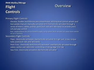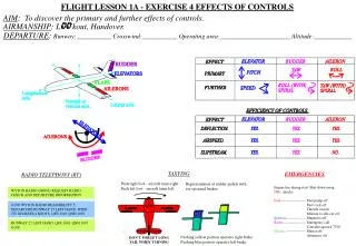
Rotor Flight Controls
Rotor Flight Controls. S64F Model Helicopter. Flight Controls. The Flight Controls consist of the following systems Cyclic Collective Directional Controls (pedals)

Rotor Flight Controls
E N D
Presentation Transcript
Rotor Flight Controls S64F Model Helicopter 7-
Flight Controls • The Flight Controls consist of the following systems • Cyclic • Collective • Directional Controls (pedals) • The systems mechanically and electrically link the cockpit controls to the main and tail rotors, through a series of rods, bell cranks, servos, pulleys, cables and wiring. Aft Seat Cyclic Right Hand Cyclic Left Hand Cyclic Right Hand Collective Left Hand Collective Aft Seat Collective Left Hand Pedals AFCS Servo Right Hand Pedals Mixing Unit Primary Servo Left Lateral Primary Servo Fore & Aft Primary Servo Right Lateral Tail Rotor Servo 7-
Main Rotor Flight Controls • The Main Rotor flight controls consist of the following: • Cyclic control system • Cyclic stick trim system • Collective pitch control system • The Left and Right seat Cyclic send mechanical signals to the AFCS through push/pull tubes and bell cranks. • The Aft seat Cyclic is entirely electric, sending signals to the AFCS through the “moog” valves. • Cyclic stick trim can be controlled by the stick trim switch on all three cyclic. • The Left, Right and Aft seat collectives send mechanical signals to the AFCS through push/pull tubes and bell cranks. 7-
Cyclic Control Cyclic • The cyclic control system provides lateral and fore and aft control of the helicopter by tilting the plane of rotation of the the main rotor blades, which moves the helicopter in the tilted direction. • Inputs to the cyclic go through the cyclic mixing unit, to the AFCS and on to the primary servos. Mixing Unit 7-
Collective Controls • The collective control system provides vertical control of the helicopter from the left, right, and aft seat control sticks, through a series of control rods and bell cranks through the AFCS then to the mixing unit. • At the mixing unit, all vertical movements of the collective stick are transmitted to the tandem main rotor servos, where the pitch of all blades are increased or decreased equally at the same time. • A friction lock is on the right hand collective stick, when applied it prevents collective creep and provides feel when collective is moved. Right Seat Collective Friction Lock 7-
Tail Rotor Controls Description • The tail rotor flight control system controls the pitch of the rotor blades and thereby the heading of the helicopter. • The system consists of the following. Left and right seat pedals, adjustments for leg length, a series of control rods, bell cranks, servos, and cables. Tail Rotor Servo Control Rod Pedals 7-
Tail Rotor Controls • From the forward quadrant in the attic, cables connect the AFCS output to the rear quadrant in the tail pylon. From the quadrant a push/pull tube connects to the tail servo. The servo hydraulically controls the pitch of the blades. • The left and right seat pedals are also connected to the wheel brake cylinders through control rods. • Tail Rotor Cables are 5/32 in diameter with a plastic coating to help protect the cable. Forward Quadrant In Attic 7-
Mixing Unit Description • The main mixing unit is mounted directly above the AFCS and is connected by control rods. It consists of a rotating shaft, arms, and bell cranks. • The mixing unit is the point where the collective controls merge with the cyclic controls. • The combined flight control movements coordinate the main rotor blades, tail rotor blades, and engine power (bias control). Bias Control Mixing unit installed In A/C 7-
Mixing Unit 7-
Collective Bias The bias cables connect to the collective bellcrank of the mixing unit and are routed through the attic to the engine bias gun on the fuel control. The collective bias allows for governing power plant performance in relation to the main rotor pitch. This Gives the engines relatively constant free turbine speeds. Mixing Unit to Bias Cables Bias Guns on Engines 7-
Flight Control Rigging • Rigging of the flight controls involves matching the neutral position of the cyclic stick, collective stick, and pedals with a corresponding neutral position on the AFCS servo, primary servos, and tail rotor servo. • The Flight control rods all have a dimension that they are set to prior to installation. They are then adjusted for rigging pin alignment. As long as 0.020 in. (.05 cm.) safety wire can not be passed through the inspection hole the control rod is acceptable. • The Bell cranks and mixing units have a hole for inserting a rigging pin insuring a neutral position. Their locations are listed in the Maintenance Manual Ch. 11. 7-
Rigging • There are some standard practices and precautions to be used during the rigging procedures. • Rigging pins should be straight, never use a bent pin. Rigging pin lengths and locations are listed in the MM Ch. 11. When installing a pin never force it into the rigging hole, or move the controls to make it fit. • Rigging blocks are identified with a part number and height. When using a rigging block the part number and height are shown in the procedure information. Make sure you have the correct block before rigging. Rigging Block P/N, height and location 7-
Rigging Tools 18 inches (45.72 cm) Rigging Blocks Rigging Pins 3.5 inches (8.89 cm) 7-
Rig Main Rotor • To Rig the main rotor controls install rigging pins and rigging blocks in the locations specified by figure 11-25 in the maintenance manual. • If any rigging pin cannot be installed, disconnect control rods from bell crank, pin the bell crank, and adjust control rods to fit. Make sure that the safety of the control rod is still good by trying to insert 0.020 (.05 cm) safety wire through the inspection hole. • Once all the rigging blocks and pins are in the controls are considered rigged. • Any checks required by the maintenance manual should be done now. (bottoming check, MRB control range and blade angles, bias control rigging check) 7-
Main Rotor Blade Angles • Once the rigging of the flight controls and servos has been completed, the blades can be checked for proper range and blade angles. • The control range for fore-and-aft, lateral, or collective is the total number of degrees a sleeve and spindle turns when the cyclic or collective stick is moved from on extreme to the other. • Blade angles are measured with the main rotor head in a specific location to the primary servos. Blade Angle 7-
Secondary Stops • Anytime the control range and blade angle has been checked or anytime a cyclic or collective housing has been changed, the secondary stops need to be checked and adjusted if needed. • There are four adjustable stops on the left and right cyclic mixing units. The stops are set to physically stop cyclic movement 0.010 inch (.025 cm) after the AFCS primary stop is contacted. • The left and right collective have two stops each. The high stop is set 0.010 (.025 cm) inch past the primary stop in the AFCS, and the low stop is set 0.125 (.318cm) past the primary stop in the AFCS 7-
Bottoming Check • A bottoming check is done on the primary servos to ensure that the internal piston does not bottom in the full up or full down position. • A bottoming check should be done when adjustments are made to the main rotor control rigging. 7-
Pylon quadrant Tail Rotor Rig Illustration • Tail rotor rigging is done anytime the requirements of a tail rotor control check have not been met or when there is doubt as to the proper operation of the tail rotor controls. • Rigging the tail rotor control system involves coordinating the neutral position of the foot pedals and the forward and aft quadrants, with the neutral position of the AFCS servo and the tail rotor controls. Tail Rotor Servo 7-
Tail Rotor Blade Angle Range • Once the tail rotor rigging has been done, blade angles need to be set. Blade angles are measured on the vernier & plate located on the tail rotor head grip, or with a propeller protractor. • A tail blade angle check is done anytime the main rotor controls have been rigged. 7-
Forward Quadrant Stops Adjustments to the forward quadrant stops set the blade angle range. The quadrant and stops are located in the attic. 7-
Pedal Stops • The pedal stops are to be adjusted whenever a blade angle check has not been met or a pedal stop bolt is replaced. • The pedal stops are set as a secondary stop to the forward quadrant. • The stops are set with a 0.010 inch (.025 cm) gap, after the pedal has been pushed to its full travel position and allowed to return indicating that it is at the AFCS internal stop. 7-
Rigging pins are required in the forward and aft quadrant when adjustments are made. The pins should have a free fit when cable tension adjustments is finished. Tail Rotor Cables NOTE Flight control cables are 5/32 inch diameter with a plastic coating. Plastic coating has no effect on tensiometer readings. When measuring cable tension with tensiometers using risers, be sure that the correct riser for the cable is used. (Riser should be sized to the cable outside diameter. For example, for 5/32 uncoated cable use 5/32 #2 riser, for 5/32 coated cable use 7/32 riser #3). • Control Cables should be changed if the plastic coating is missing or it is not possible to view cable through coating. 7-