Download
1 / 14
140 likes | 230 Vues
This outline covers safety measures, equipment setup, and protocols for a 3He injection test. Includes details on magnets, cryogenics, pNMR, and safety precautions for handling helium gas and protecting the ABS vacuum system. The document also discusses pressure relief mechanisms, tricoil magnet system specifics, and considerations for minimizing induced voltage in wire connections. Design work is nearing completion for fabrication and assembly, with the injection test scheduled for the end of July.

E N D
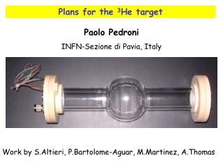
Preparation for the 3He Injection Test 05/2008 Duke D. Dutta*, H. Gao, M. Busch, Q. Ye, X. Qian, W. Zheng, X. Zhu (Duke University) ASU, BU, Caltech, LANL, MIT, MSU, NCSU, SFU And others in nEDM collaboration *Mississippi State University.
Outline • Introduction • Safety • Magnets • Glassware • Cryogenics • pNMR • Summary
Helium gas Filling pipe To ABS Helium bath vessel 50K 4k Heat exchanger 1.3k 0.7k 0.24k Film burner Pyrex cell Dilution refrigerator Helium @0.35k tricoil
Update • Problem with jacket pyrex cell • Seal <1K and safety when boil off • Cool the cell with OFHC copper foil To ABS DR 1K pot Cs ring Filling pipe for L-He Copper foil to cool the cell Measurement cell @.35K DR MX at 0.24K
Safety I: Boil off of LHe within pyrex cell • 23.58 cc LHe within pyrex cell • boil off rate: ~1 mol/s • Heat rate: 60000 W/m2, in worst case • Effuse through ABS beamline, pressure difference ~25.2 Pa • Gas density at 273 K and 1 atm • Id: 0.04 m, L=1.0 m • Flow velocity: 17.8 m/s • Reynold constant: Re = 6842.4 • Resistance coefficient, K=0.9 • From T. Ito and Applied Fluid Dynamics Handbook • Effect of thermal baffles not included
Protection for ABS vacuum system • A pneumatic valve to protect ABS beamline • A rupture disc for pressure relief ABS 2” If P>10-5 torr Activate the Pneumatic valve 5” 2” Gate valve Vacuum Gauge and pump 5” Rupture disk/ Pressure relief Non-magnetic Pneumatic valve ABS low Beam line Catastrophic Boil off
Siphon pipe to fill LHe into tricoil can Pipe for safety venting Heat rate: 2 kW/m2 Pressure drop: 5.5 psi Gas density@50K,1atm By J. Long Venting velocity: 97m/s 1.375” ID, 45” length Reynold number: 5.7x10⁵ resistant coefficient: 0.49 Rupture disc@4K Avoiding Taconis resonance Safety II: boil off of LHe within Tricoil can Siphon pipe Vacuum vent pipe
Energy within tri-coil: 714.15J Energy within transport solenoid coil: 6.3mJ, negligible Quench will evaporate 2.84 liter of He gas at 4K Amount to 8.67 mol He The volume of tri-coil container: ~17 liter Bottom :14 lit, top: 3 lit. The pressure will increase by <50% Assume space of coil : 7 lit Acceptible to tricoil vessel FEA analysis done by E. Iholff Safety III: No problem with superconductor quench Pressure <2atm
Tricoil Magnet system • Tricoil current lead • 300K to 50K: copper wire, #11 AWG • 50K to 4K: silver wire with filaments of HTS ceramic (BiPbSrCaCuO) • Low thermal conductivity • From American Superconductor • Solder with eutectic InAg with no flux
Heat load to DR mix:~ 5mW ~2.5mW from superfluid film burner By G. Seidel 0.5mW for pNMR and support 1.1mW for gas introduction tube 13.8mW cooling power @0.24K Cs ring to slow down superfluid flow rate Torch to chase Cs vapor Dry ice to condense Cs effectively Sealing test undergoing Pyrex to copper adapter After fail and try, kapton gasket seals well with copper flange Cryogenics Cs ring Made by dry ice Epoxy 2850GT Kapton gasket
Faraday cage Two tunable capacitor Resonant coil Copper enclosure@1.3K Semi-rigid coax Center: Ag coated BeCu Dielectric: teflon Sheath: BeCu From D. G. Crabb, UVA Weakly magnetized SS Tosca simulation by Tim, ASU pNMR system Faraday cage
Wire connection for temperature sensors • Thermometer leads: twisted pair , Phosphor bronze • Suggested by S. Williamson • Noninductive winding scheme • Minimizing induced voltage due magnetic flux change • Voltage wires and current wires thermal anchor separately • Wire lengths for thermal anchoring (300K to 4K) • 1.1cm for #32 AWG • 3.8cm for #24 AWG Heat sink post
Summary Design work is almost done, ready for fabrication and assembling. Injection test will be ready in the end of July