Download
1 / 24
250 likes | 422 Vues
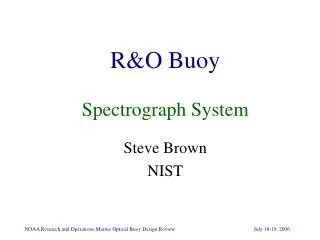
R&O Buoy Spectrograph System. Steve Brown NIST. Research and Operations Objectives. Transition MOBY vicarious calibration capabilities for NPP/NPOESS VIIRS & GOES-R HES Like to maintain high spectral resolution for good matching to satellite bands

E N D
R&O BuoySpectrograph System Steve Brown NIST
Research and Operations Objectives • Transition MOBY vicarious calibration capabilities for NPP/NPOESS VIIRS & GOES-R HES • Like to maintain high spectral resolution for good matching to satellite bands • Adapt MOBY technology for complex coastal validation activities for GOES-R (e.g. HES) • Two spectrographs: one blue and one red • Reduce MOBY operational costs • Reduce the size of the buoy • Operational for longer periods of time between servicing (extend period from 3 mos. to 6 mos.) • Anti-bio-fouling more critical • Instrument stability and monitoring more critical
Reduce the measurement uncertainty • Laboratory • Calibration source • Stray light • Environmental • Bio-fouling • Self shading or shadowing • Noise from wave-focusing, etc. • MOBY: single channel spectrograph with optical fiber multiplexer • each arm, each sensor data taken sequentially • It can take 20 minutes for a scan. • New Buoy: Simultaneous Data Acquisition
MOBY Uncertainty Elements Addressed with the new Optical System • Reduce the stray or scattered radiation in the system • Eliminate dichroic filter • Two separate spectrograph systems • One for blue water • Second to be added for coastal regions • Systems designed for simultaneous acquisition (all ports) • Ideally like to have 8 ports to minimize self-shading effects • Minimum # of ports required is 4
R&O Optical System Breadboard (Spring 2005) • ISA (Jobin Yvon) f/2 spectrograph with reflective concave holographic grating; 25 mm slit • Andor 1024x256 cooled CCD array, 25 mm pixels • Four separate 1 mm diameter optical fiber inputs along entrance slit
Multi-track fibers • Breadboard system had 1 mm fibers separated by ~500 mm Image expanded to 1 % full scale
Breadboard System Performed Well in the Laboratory'along-track' scattering – in the dispersion direction • Stability, system response, and signal to noise ratio adequate for ocean color measurements • Spectral stray light from optical system is better than MOBY • Spatial stray light correction algorithm (to account for cross-track coupling) developed and successfully implemented
At-Sea Tests The breadboard system was implemented with four inputs and tested in Case 1 waters off Oahu in August 2005. The inputs were Es, Eu, Lu (0.75m) and Lu (3.25 m).
Preliminary Conclusions (end of August 2005) • Breadboard System • All-fiber input simplified optical design • Superior stray light (compared to MOBY) • A simple 2D stray light model was implemented • Satisfactory dynamic range and sensitivity demonstrated • Successfully balanced individual throughputs resulting in the same integration time, independent of Es or Lu • Simultaneous acquisition successful. • A full measurement, comparable to a MOBY data set, takes about 20 sec, not 20 min. • Meaningful reduction in measurement uncertainty achieved (Ken Voss) • Outstanding issues: • Desirable to have eight fiber inputs to reduce shadowing effects • Increased spectral resolution • Resolution degraded for top and bottom channels • Desirable to change CCD from Andor to Apogee Alta system • Heritage: U of Miami Group is experienced with Apogee systems; some control software has been written • Size: Andor power supply a disadvantage for buoy operation
Spectral Resolutioncompared with MOBY Breadboard System Image Qualitybetween Tracks
Spectrograph vendor search • Multi-channel input: • minimum of 4 channels; 8 channels preferable • High throughput, f/# 2.4 or lower • High resolution • Approx. 1 nm ideal • 2 nm might be acceptable • Software control over the acquisition • Ethernet-based • Compact – size is an issue • Time and money concerns, looking for Commercial Off-the-Shelf (COTS) systems if possible • Ruggedized or ruggedizable for field deployment • Heritage matters
Image Plane • Defined by choice of CCD • 1024 by 256 element, 25 mm pitch CCD • 25 mm (dispersion) x 6 mm (for multi-channel acq) • Systems 1:1 imaging • 25 mm pixel > 25 mm entrance slit System f/# • For simplicity and to maximize throughput, we wanted the f/# of the system to match or be slightly smaller than the f/# of the input fiber • Fused silica fiber, NA of 0.22 or f/#=2.3 • Spectrograph f/# of 2.4 or smaller
System resolution defined by spectral band pass matching requirements • High Resolution Spectra Convolved to Sensor’s Spectral Band Pass. • Single site can service multiple sensors • MODIS, MERIS, SeaWiFS > VIIRS, GOES-R HES, etc. MODIS&SeaWiFS: 10 nm bands VIIRS: 20 nm bands HES: 20 nm threshold 10 nm goal MOBY: 1 nm bands > R&O: 2 nm bands NASA new Ocean Color Satellite SeaWiFS-like: 10 nm bands NASA: Vicarious calibration buoy: ~ 1 nm resolution R&O - 2 nm resolution maybe ok NASA - 1 nm resolution
Spectral Bandpass Matching IllustrationMODIS Terra In-Band Wavelength Uncertainty
Multi-track fiber consideration • 4 input channels • keep 1 mm core diameter fiber • or go to 500 mm fiber • 8 input channels • 500 mm fibers; 250 mm spacing Future consideration • New 1024 by 512, 25 mm pitch chip coming out for the Apogee system (est. release this fall) • 12 mm slit height&image plane possible
Vendor Search • Newport, ISA (JY), Zeiss, TECUSA, Headwall, Satlantic, Kaiser, Optronic, Instrument Systems … • Headwall, Jobin Yvon, & Kaiser • Headwall provided aircraft instruments • Same optical configuration as MOBY • Kaiser • Axial transmissive system • Developed an in-situ ocean Raman system for MBARI • Jobin-Yvon • We had evaluated a JY system and it performed well.
Headwall Photonics • Image plane not matched (6 mm horizontal, dispersion direction) • Spectral coverage not well-matched to MOBY requirements • Resolution: 2 nm at best • Has required resolution • Needs custom grating • No characterization data • Better horizontal image plane
Jobin Yvon • CP140 • COTS not a perfect match: spectral coverage&resolution • Custom gratings possible, but expensive (>10 K) with several months delivery • f/2.4; simple, compact, good optical quality • Aberrations affect imaging away from center 2 mm • We need to develop input and CCD mounts/holders, etc. • CP200 • possible better imaging (larger system)
Output Plane Multi-element Lenses Holographic Transmission Grating Entrance Slit Volume Transmissive Gratings • Axial Transmissive Design • Offer both standard and custom gratings • No imaging degradation over the full slit: > 10 mm • High Throughput: f/#=1.8 • High Spectral Resolution: ~ 1 nm • Minimal # of optical elements: No Moving Parts • Improved Thermal Stability over Czerny-Turner design • Stray light < 1e-4 • 50 channel system demonstrated • Rugged Compact Design • Been deployed in an underwater Raman system (by MBARI) COTS: Kaiser Optical Systems
Kaiser Optical Systems • Each grating a ‘master’ • Relatively inexpensive and quick to modify grating specifications • Respond to changing vicarious calibration requirements • Different gratings can be placed vertically within a single larger grating plane • Visible and NIR system within the same instrument
R&O Prototype: Status on Spectrograph Systems • The JY/Andor prototype is in-house • Successful characterization measurements & field trials with JY system • One Kaiser system, new JY system ordered • Two Apogee camera systems ordered • Multi-track fiber inputs ordered (Romack) • One 8-channel input system • One 6-channel input system • All due in ~ September