LOAD BALANCING SWITCH
Project POSTER. By: Maxim Fudim Oleg Schtofenmaher Supervisor: Walter Isaschar. Winter - Spring 2008. LOAD BALANCING SWITCH. Abstract. Software solutions for real-time are too slow Power dissipation limits work frequencies

LOAD BALANCING SWITCH
E N D
Presentation Transcript
Project POSTER By: Maxim Fudim Oleg Schtofenmaher Supervisor: Walter Isaschar • Winter - Spring 2008 LOAD BALANCING SWITCH
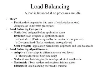
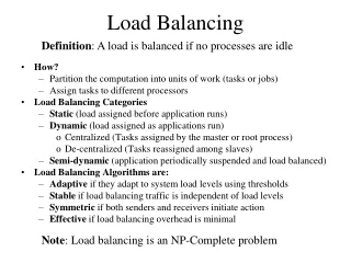
Abstract • Software solutions for real-time are too slow • Power dissipation limits work frequencies • Greater computing power needed • H/W accelerators may improve S/W processes • Multi-core, multi-threaded systems are the future
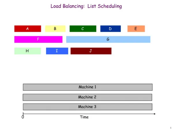
Project Goals • Multiprocessor environment for parallel processing of vectors data stream • Maximal Throughput • Configurable hardware • Expandable design • Statistics report
System specifications • SW over transparent HW • Interface over PCI • 1 Mbit/sec input stream • Vectors of 8 ÷ 1024 chunks • Variable number of processors • System spreads over multiple FPGAs
Problem • How to manage Data stream? • How to manage multiple parallel units? • How to achieve full and effective utilization of resources?
Solution (Top Level) • Board Level Load Balancing Switch • One system input and output to PCI • Distribute vectors among classes • Local buffers for chip data
Solution (Chip Level) • Chip Level Load Balancing Switch • Converting shared resources to “personal” work space. • Cluster ‘s organized VPUs • Monitoring for each unit’s load • Smart arbitration • Flexible and easy configuration
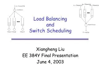
Solution - Tree Distribution Switch SW/HW interface Class of Service Distribution LBS Arbitration LBS Arbitration LBS Arbitration Clusters of VPUs Clusters of VPUs Clusters of VPUs Clusters of VPUs Clusters of VPUs Clusters of VPUs Clusters of VPUs Clusters of VPUs Clusters of VPUs
Three level Architecture • Provide level for packets management ( Classes ) • Type, Size, Priority of Data • Provide level for organizing various processing units ( Clusters ) • Speed , Quantity, Resources of Processors • Provide level for fine tuning ( VPUs ) • Algorithm, HW accelerating
Implementation • Multi chip system connected over two busses • Input and Controls over Main Bus • Output via streamed neighbored busses • Local FIFOs for every chip/class • Classifier for packet management • SW configurable controls • Cluster organized VPUs with in/out arbitration • Watchdogs & Statistics Gathering
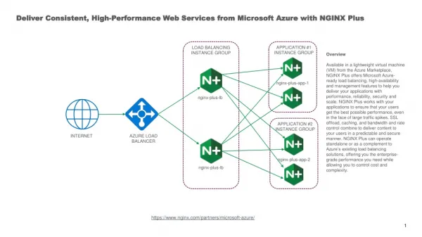
Board Level diagram Stratix II 180 Stratix II 180 Stratix II 180 Stratix II 180 Ring Bus Ring Bus LBS1 LBS2 LBS3 LBS4 Classifier MainBus : Data In and Controls DDR2 DDR2 DDR2 DDR2 DDR2 DDR2 DDR2 DDR2 PROCStar II Input vectors Output reports Per LBS registers PCI Bus S/W emulator or H/W DSP system
Single FPGA Top Diagram NIOScluster NIOScluster NIOScluster NIOScluster DDR2 Controls Bank A NIOScluster NIOScluster NIOScluster NIOScluster Bus Control Block Load Balancing Switch (LBS) I/O – LBS Control Block Data flow NIOScluster NIOScluster NIOScluster NIOScluster DDR2 Controls Bank B NIOScluster NIOScluster NIOScluster NIOScluster LBS 1-4 Stratix II 180 FPGA
Data Packet Format …… Header Tail Data 1 to N of 32-bit Words Header : SW/HW Control 1-bit Unused Nios Number Data Length N Vector ID/Command Type Type 1-bit (Data/Command) Version 4-bit 8-bit 16-bit 32-bit Tail : Sync Data
LBS Class Top Level View FIFO Input Port Busses Control Block Input data bus Cluster Arbiter Cluster Arbiter Cluster Arbiter Input Reader NIOS II System NIOS II System NIOS II System Control Main Controller unit Statistics Reporter Control Control and Status Output Writer Control FIFOOutputPort Muxed output data bus Stratix II FPGA
Organization of VPU’s(Vector Processing Units) • NIOS VPUs joined into the clusters • Constant number of Clusters • Parametric number of NIOS VPU’s in cluster • Parametric control & distribution logic • Various configurations of NIOS • Static/Dynamic Priority Arbitration
LBS Units DescriptionVPUs: NIOS System • Single processor with in/out buffers • HW accelerated system • Shared resources system with mutex • Multi- processors system with number of ports to Cluster
Resource Usage Resource usage data for 6 VPU system VPU resource usage is based on basic VPUs and may be decreased by advanced configurations and policies.
Performance of LBS • Theoretical Throughput: 100MHz x 64bit = 6.4Gbit/s • Arbitration and routing latency: 2-4 cycles in average • 60% effective bandwidth utilization for short vectors, up to 98% for long vectors • 1Mbit/s – 400 Mbit/s real throughput • PCI and slow algorithms = bottlenecks
Performance for short vectors Time and throughput for 1000 vectors of 4 chunks each VPU performance is based on basic VPUs and RR arbitration and may be increased for giving workload after perf. analysis by defining advanced configurations and policies.
Performance for medium vectors Time and throughput for 1000 vectors of 200 chunks each VPU performance is based on basic VPUs and RR arbitration and may be increased for giving workload after perf. analysis by defining advanced configurations and policies.
Performance for long vectors Time and throughput for 100 vectors of 1000 chunks each VPU performance is based on basic VPUs and RR arbitration and may be increased for giving workload after perf. analysis by defining advanced configurations and policies.