Download

1 / 13
130 likes | 314 Vues
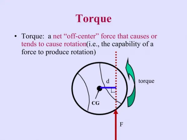
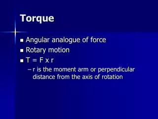
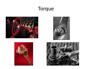
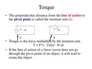
Introduction to Torque. The measure of a force's tendency to produce a rotation about an axis is called torque. That is, if a force is used to begin to spin something, or to attempt to spin something, a torque is generated.

E N D
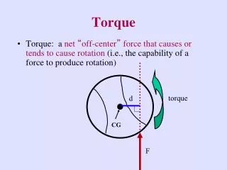
Introduction to Torque The measure of a force's tendency to produce a rotation about an axis is called torque
That is, if a force is used to begin to spin something, or to attempt to spin something, a torque is generated.
A torque would also be generated if a force was used to stop something from spinning.
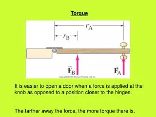
For example consider a stick or board that is placed horizontally and is attached to an axis at its center so that it can rotate If a force pulled down on the right side of this board. then it would rotate clockwise. The force acts perpendicular to the torque arm. And the distance from the fulcrum to the applied force is the radius. The torque arm is also called the lever arm.
For our purposes here, consider the lever arm to have no mass. That is, it is in equilibrium and therefore has no rotation Because no force is being applied to either side of the lever arm. All the mass is concentrated at the fulcrum. This is know as the center of mass or center of gravity. All the downward forces are parallel to each other and because they are all of equal value On the left and right side of the fulcrum, the object will not rotate.
If we added a mass to the right side of the lever arm, we would see that the force causes a clockwise torque to be placed on the lever arm. This torque is calculated by multiplying the length of the torque arm times the size of the force. If the torque arm was 3.0 meters long and the size of the force was 4.0 Newtons, then the calculation for the torque would look like this:
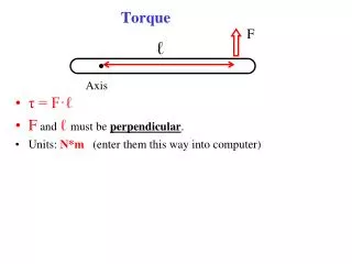
You see that the formula in the previous slide was T = F x d But it is really written to be T = F x d x sinq This makes sense because if a force is applied at 90 degrees to the lever arm, then the sine of 90 is 1. So it is if you just leave out the sine of the angle, but you can not do that because force is being applied at some angle, perpendicular to the radius or not. Lets say I push in towards the center along the radius or pull straight out – then the sine of the angle is sin0 or sin180 which equal zero and no rotation exists because of the direction of the force.
Sometimes torque can be created on both sides of the fulcrum In this case, you must first identify the fulcrum (pivot point) and add up all the forces on the right and left of the fulcrum in order to determine the rotation of the lever arm. If for example, each of the masses above is 1N each, what would the direction of rotation be is each dot represents 10cm from the pivot point? There would be no rotation because the torques would be equal.
Sometimes, when we want to stop a lever arm from rotating we place two fulcrums under the lever arm like a bridge supported by the two sides of a ravine or a saw horse. This type of support keeps the bridge from falling in to the ravine. The support has to be able to maintain the force pressing down on it from the bridge or any vehicles. If a bridge was 60m long and weighed 3000N then each support would hold FA x 60m = 30m x 3000N because that is the distance to the center of mass to each pivot point. Solving for F, we find the force needed to hold up each side of the bridge.
It gets more complicated if there is some mass on a bridge between the two supports. In this case we would want to know how much force is pushing down on each support as the car is at some distance from one side or the other. To do this you would have to find the net force acting on each support This is done by selecting one side and treating it as a pivot point. The opposite side is where the force is being applied. You then simply add the F x d of the car to the pivot point and the F x d of the bridges center of mass to the same point and set it equal to the Force you want to find x the total distance.
But remember to find the force exerted on the other side of the bridge too. This is accomplished by finding the distance to the other side and multiplying time the force of the car plus the F x d of the bridge. Say a car weighing 500N is 10m from the left side of a 40m long bridge that is 3250N. Find the force exerted on each support. For the left side it would be; FL x 40m = (30m x 500N) + (20m x 3250N) For the right side it would be; FR x 40m = (10m x 500N) + (20m x 3250N) Solve for F to find the force exerted on each side Also remember F net = the sum of all forces
http://id.mind.net/~zona/mstm/physics/mechanics/forces/torque/introductionToTorque.htmlhttp://id.mind.net/~zona/mstm/physics/mechanics/forces/torque/introductionToTorque.html