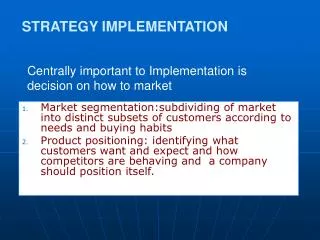
The Implementation Strategy
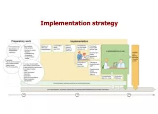
The Implementation Strategy. Proposed SLAC Controls Upgrade December 1, 2010 Ray Larsen. Outline. Existing System MTCA Module Development Single Station Upgrade Demo Plan Production & Test Plan Steps to Installation & Switchover (TH). Existing System.

The Implementation Strategy
E N D
Presentation Transcript
The Implementation Strategy Proposed SLAC Controls Upgrade December 1, 2010 Ray Larsen
Outline Existing System MTCA Module Development Single Station Upgrade Demo Plan Production & Test Plan Steps to Installation & Switchover (TH) Controls Upgrade Implementation
Existing System • Every RF station has 2-bay rack for controls • 8 Stations per each of 30 Sectors • Includes 6-8 RF Stations for each injector • New upgrade RF plus accelerator controls can fit in single rack Controls Upgrade Implementation
Klystron Gallery Layout Short cables top of penetration would need elongation to new rack Controls Upgrade Implementation
SLED WG & Cable Penetration to Tunnel RACKS MAGNET TANK
Existing Linac Klystron Station RF Control, Monitoring, and Interlocking System IPA Chassis Controls RF Phase and Amplitude PAD Chassis Measures RF Phase and Amplitude PIOP CAMAC Module Controls IPA, PAD, and MKSU. Interface to control system MKSU Chassis Interlock and Control for Klystron SLED Support Systems Existing Controls Racks New system will combine the PAD, IPA, and part of the PIOP into the RF Control System Controls Upgrade Implementation
PIOPs (4) PDU Timing Controls Upgrade Implementation
Existing Rack Issue • Racks are sub-standard in meeting code, cooling and filtering protection • Ideally would install modern environmentally controlled closed racks • Not in budget & some stations lack space • Proposed work-around • Refurbish present rack to bring ~up to code, plus add power for local solenoid PS plan (new) • Insert secondary enclosure inside rack with crate cooling, sealed from dirty air, w/LCW air-water temp control Controls Upgrade Implementation
2. MTCA Module Development The following show the MTCA development strategy for in-house RTM design. We are procuring generic COTS AMCs each of which will support a number of applications via RTMs Controls Upgrade Implementation
MTCA Engineering Reference Design • Double-wide plus RTM provides excellent analog space, ground noise control, crosstalk • AMC space fully backward compatible with industry single-wide designs • Reference Design complete w/ supporting FW-SW environment enables engineers • to focus on payload design w/ power, IPMI basic infrastructure standardized
Adapting Controls Subsystems • Port existing front end interfaces onto RTMs • 4 & 10 Ch Fast ADCs w/DAC RTM adapters: • Stripline BPMs (2 types) • Toroids (2 types, Linac & Beam Containment), Profile Monitor Gated ADC (Same as above) • RF Feedback • 3-Industry Pack RTM Adapters: 4. Profile Monitor Beam Length (BLEN) 5. Vacuum gauge controller interface 6. Vac-ion pump controller interface 7. Wire scanner movers (Hytek) • PMC Card AMC Adapter 8. Fast Frame grabber for Profile Monitor
Beamline BPMs, Toroids, Gated ADCs • Strategy: • Encourage Industry to provide key generic complex AMC modules • Develop 2 or more sources • Encourage multiple lab- supported specifications (Struck, Vadatech, Libera)
LLRF System, Feedback Apps (Struck, Vadatech Libera)
Beamline Instruments via IP Adapter (TEWS, Vadatech)
High BW Frame Grabber PMC Adapter (TEWS, Vadatech)
3. Single Station Upgrade Demo Plan • Proposed staging plan (Station 28-2): • Integrate Controls and RF subsystems separately on identical MTCA platforms • Controls Infrastructure Team supports both with test hardware, firmware, IPMI, low and high level software (in process) • Subsystems integrated, lab-tested separately • Temporary air-water cooled rack installed in 28-2 • Merge tested subsystems in 28-2 • Test each offline, then together online with beam Controls Upgrade Implementation
Single Station Components (Typ.) • Station Control Functions • Klystron-Modulator Interface (MKSUII) • Interlocks & monitoring • Solid state sub booster monitoring • Local displays & controls • Controls & Monitoring (MTCA) • Status of RF Controller via ADC-DAC RTM • Heater & Solenoid power supplies - SLED Tuners • MK Interlocks – Vacuum – Temperatures • BPMs – wire scanners – profile monitors • Network interface to/from modulators Controls Upgrade Implementation
Test Station BD – RF & Accelerator 40ft ACCEL.SECTION INSTRUMENTS & CNTRLS MAIN DRIVE LINE SYNC CLOCKS & LO GENERATION BPMs Toroids Wire Scan Profile Mon. Vacuum Power Supplies BCS Temperature Controls Upgrade Implementation
Station Crate Layout (Typ.) SPARE SLOT Infrastructure Pwr, MCH, IOC, Timing RF Fdbk Controls Modules (Typ.) Redundant MCH, Pwr Options Controls Upgrade Implementation
Side View Crate, AMC, RTM Note – All I/O in Rear; both AMC, RTM Hot Swappable Controls Upgrade Implementation
MTCA 12-Slot Shelf & Modules 6 Slot Crate w/ AMC & RTM (Schroff) 12 Slot Crate & Front-Rear Fan Tray (Schroff)
Upgraded Station Rack Profile Controls Upgrade Implementation
In-Rack Crate Enclosure RF CABLES TO/ FROM TRAYS REAR I/O CABLES TO/FROM RTM’S WATER COOLED ENCLOSURE CABLES TO/ FROM TUNNEL Controls Upgrade Implementation
4. Production & Test Plan • Procurement Controls • All MTCA components except RTMs purchased from vendors • Arrive tested including basic SW, FW • RTMs designed in house relatively simple; vendors will be interested to bid on providing tested units. • Otherwise contract fabrication & test in-house • Rack enclosure with heat exchanger will be contracted to a chassis manufacturer offering the service Controls Upgrade Implementation
Generic Application AMC’s • Three AMC’s with RTMs serve all RF needs: • Fast ADC DAC AMC module for RF phase, amplitude control and feedback • General Analog-Digital Industry Pack (IP) carrier AMC to serve all miscellaneous monitoring and controls • PMC Adapter to easily port existing designs in LCLSI • Item 1 delivered & in test; item 2 quote in hand for order; item 3 exists and needs porting to RTM version • Standards Goal: Procure key modules from at least 2 vendors Controls Upgrade Implementation
Struck SIS 8300 RF Digitizer RTM Connector AMC Connector 10 Ch 16 bit 125 MSPS 2 Ch 16 bit DAC output Virtex 5 FPGA Controls Upgrade Implementation
Timing Module – Stockholm U. Timing AMC (University of Stockholm) • Fiber optic links w/ drift compensation • ps stability • AMC module is receiver and transmitter • Clock, trigger and event distribution Controls Upgrade Implementation
Production 2 • RF Chassis (2) • 2 separate chassis are being designed, one with RF circuitry and water-cooled heat sink, the other the MKSUII protection chassis • These are custom units deemed to be not suitable for MTCA packaging partly due to special constraints • Fabrication for quantities will be less amenable to outside fabrication and testing except for ADC-DAC which is MTCA AMC-RTM. • Will seek out vendors who can provide integrated service and back up with in-house shop and production testing. Controls Upgrade Implementation
Production 3 • Pre-test and field integration • Since installing into existing racks, no normal luxury of pre-loading racks in shop, testing before field installation • Will increase Davis-Bacon costs labor in field • All field cable retrofitting done by skilled contractors or SLAC personnel (bad contractor performance on controls cables is a given) • All chassis units fully pre-tested, calibrated before install • Purchased modules and RTMs checked in crate and crate installed • RTM cables prefab & tested before field install • Following slide shows production install flow Controls Upgrade Implementation
Production & Installation Summary • Production and installation scenarios can be highly flexible due to modular nature of accelerator and small chassis and modular assemblies involved • Rack issues in gallery still need work (with PCD) toward optimum solution – cannot grandfather sub-standard units forever • Developing 2 or more vendors for key infrastructure and controls applications modules • In next section T. Himel discusses strategies for changeover within constraints of running LCLS and FACET programs Controls Upgrade Implementation
5. Steps to Installation & Switchover - Contributed by T. Himel Controls Upgrade Implementation
Steps to switchover • First, get all multi-sector or multi-system control of FACET handled by new LCLS style applications (mainly EDM and Matlab) • This was mostly the case for LCLS before our upgrade started. A few had to be moved from old to new. An effort will be required to extend these to FACET, but much smaller than originally doing it for LCLS. The physicists and OPS are used to this and will want FACET to head in that direction anyway. • There are only two ways these applications have to access SLC data: SLCCAS (SLC Channel Access Server) and AIDA.
Installation during FACET era FACET will be running 4 months a year for the next 5 years using sectors 0-20 and the damping rings. The exact schedule is unknown, but worst case is two 2-month runs each year. (Linac startup time is so long, I cannot imagine more shorter runs.) These downtimes are too short to install the full upgrade during a single downtime. Hence we need a way to do partial installs and run FACET with mixture of two control systems.
Installation during FACET era We are doing something similar with the phase I upgrade in sectors 21-30 right now. It is somewhat easier than what we will be doing for FACET because we only have to move one cable (the CAMAC cable) per sector to switch between old and new control system. It is somewhat harder because LCLS is much less tolerant of downtime than FACET. We are, however, set up to be able to run LCLS with sectors split between old and new control systems. We will use a similar method for FACET.
Steps to switchover • Second, setup a PVgateway to translate PV requests heading towards SLCCAS. • SLCCAS provides read-only access to items in the SLC DB by responding to broadcasts for PVs. • These will be channeled though a PVgateway whose setup can be easily changed to either get the data from SLCCAS or to provide nothing so that the data will instead come from newly installed µTCA IOCs.
Steps to switchover • Third, setup AIDA so it can read and write the data it handles from either the new or old control system. (This has been done for klystron and timing control for Phase I) • A small quick DB change is then used to tell AIDA to change which control system it uses to service requests it receives.
Steps to switchover Next, during a long downtime we install new hardware for whatever sectors and systems we have time and budget to do. We provide EDM screens for detailed control of the new devices. We modify the PVgateway and AIDA setups to indicate the new hardware should be used. Checkout as much as we can before FACET turn-on. Schedule check-out time during the FACET turn-on Repeat above steps for other systems/sectors/downtimes until done.
END OF SLIDES Controls Upgrade Implementation