Download
1 / 20
200 likes | 294 Vues
This chapter delves into determining mass moments of inertia for rigid bodies, applications, and calculations involving force and acceleration. Learn principles like the parallel-axis theorem and analysis procedures for various body shapes.

E N D
Chapter 6 Planar Kinetics of a Rigid Body: Force and Acceleration Dr Fauziah Mat Applied Mechanics Division School of Mechatronic Engineering Universiti Malaysia Perlis (UniMAP) fauziah@unimap.edu.my
MOMENT OF INERTIA • Today’s Objectives: • Students will be able to: • Determine the mass moment of inertia of a rigid body or a system of rigid bodies. • In-Class Activities: • Applications • Mass Moment of Inertia • Parallel-Axis Theorem • Composite Bodies • Group Problem Solving
APPLICATIONS The large flywheel in the picture is connected to a large metal cutter. The flywheel mass is used to help provide a uniform motion to the cutting blade. What property of the flywheel is most important for this use? How can we determine a value for this property? Why is most of the mass of the flywheel located near the flywheel’s circumference?
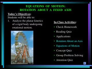
APPLICATIONS (continued) The crank on the oil-pump rig undergoes rotation about a fixed axis that is not at its mass center. The crank develops a kinetic energy directly related to its mass moment of inertia. As the crank rotates, its kinetic energy is converted to potential energy and vice versa. Is the mass moment of inertia of the crank about its axis of rotation smaller or larger than its moment of inertia about its center of mass?
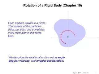
MASS MOMENT OF INERTIA Consider a rigid body with a center of mass at G. It is free to rotate about the z axis, which passes through G. Now, if we apply a torque T about the z axis to the body, the body begins to rotate with an angular acceleration of . A body that experiences rotational motion caused by moment M, is governed by an equation M = I T and are related by the equation T = I . In this equation, I is the mass moment of inertia (MMI)about the z axis. The MMI of a body is a property that measures the resistance of the body to angular acceleration. The MMI is often used when analyzing rotational motion.
MASS MOMENT OF INERTIA (continued) Consider a rigid body and the arbitrary axis P shown in the figure.The MMI about the P axis is defined as I = m r2 dm, where r, the “moment arm,” is the perpendicular distance from the axis to the arbitrary element dm. The mass moment of inertia is always a positive quantity and has a unit ofkg · m2orslug · ft2.
MASS MOMENT OF INERTIA (continued) The figures below show the mass moment of inertia formulations for two shapes commonly used when working with three dimensional bodies. These shapes are often used as the differential element being integrated over an entire body.
PROCEDURE FOR ANALYSIS When using direct integration, only symmetric bodies having surfaces generated by revolving a curve about an axis will be considered here. • Shell element • If a shell element having a height z, radius r = y, and thickness dy is chosen for integration, then the volume element is dV = (2py)(z)dy. • This element may be used to find the moment of inertia Iz since the entire element, due to its thinness, lies at the same perpendicular distance y from the z-axis. • Disk element • If a disk element having a radius y and a thickness dz is chosen for integration, then the volume dV = (py2)dz. • Using the moment of inertia of the disk element, we can integrate to determine the moment of inertia of the entire body.
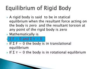
PARALLEL-AXIS THEOREM If the mass moment of inertia of a body about an axis passing through the body’s mass center is known, then the moment of inertia about any other parallel axis may be determined by using the parallel axis theorem, I = IG + md2 where IG = mass moment of inertia about the body’s mass center m = mass of the body d = perpendiculardistance between the parallel axes
Radius of Gyration The mass moment of inertia of a body about a specific axis can be defined using the radius of gyration (k). The radius of gyration has units of length and is a measure of the distribution of the body’s mass about the axis at which the moment of inertia is defined. I = m k2 or k = (I/m) RADIUS OF GYRATION AND COMPOSITE BODIES Composite Bodies If a body is constructed of a number of simple shapes, such as disks, spheres, or rods, the mass moment of inertia of the body about any axis can be determined by algebraicallyadding together all the mass moments of inertia, found about the same axis, of the different shapes.
EXAMPLE I Given: The volume shown with r = 3000 kg/m3. Find: The mass moment of inertia of this body about the y-axis. Plan: Find the mass moment of inertia of a disk element about the y-axis, dIy, and integrate.
1 1 rpx4 rp p(3000) 8 ò ò = = = = Iy dy y dy 523.6 kg•m2 2 2 18 0 0 EXAMPLE I (continued) Solution: The moment of inertia of a disk about an axis perpendicular to its plane is I = 0.5 m r2. Thus, for the disk element, we have dIy = 0.5 (dm) x2 where the differential mass dm = r dV = rpx2 dy.
EXAMPLE II Given: The pendulum consists of a slender rod with a mass 10 kg and sphere with a mass of 15 kg. Find: The pendulum’s MMI about an axis perpendicular to the screen and passing through point O. Plan: q r p Follow steps similar to finding the MoI for a composite area (as done in statics).The pendulum’s can be divided into a slender rod (r) and sphere (s).
EXAMPLE II (continued) Solution: 1. The center of mass for rod is at point Gr, 0.225 m from Point O. The center of mass for sphere is at Gs, 0.55 m from point O. 2. The MMI data for a slender rod and sphere are given on the inside back cover of the textbook. Using those data and the parallel-axis theorem, calculate the following. IO = IG+ (m) (d) 2 IOr = (1/12) (10)(0.45)2 +10 (0.225)2 = 0.675 kg·m2 IOs = (2/5) (15) (0.1)2 + 15 (0.55)2 = 4.598 kg·m2 3. Now add the two MMIs about point O. IO = IOr + IOs = 5.27 kg·m2
GROUP PROBLEM SOLVING Given:The pendulum consists of a 5-kg plate and a 3-kg slender rod. Find: The radius of gyration of the pendulum about an axis perpendicular to the screen and passing through point G. Plan: Determine the MMI of the pendulum using the method for composite bodies. Then, determine the radius of gyration using the MMI and mass values.
GROUP PROBLEM SOLVING (continued) Solution: 1. Separate the pendulum into a square plate (P) and a slender rod (R). 2. The center of mass of the plate and rod are 2.25 m and 1 m from point O, respectively. y = ( y m) / ( m ) = {(1) 3 + (2.25) 5} / (3+5) = 1.781 m
GROUP PROBLEM SOLVING(continued) 3. The MMI data on plates and slender rods are given on the inside cover of the textbook. Using those data and the parallel-axis theorem; IP = (1/12) 5 (0.52 + 12) + 5 (2.251.781)2 = 1.621 kg·m2 IR = (1/12) 3 (2)2 + 3 (1.781 1)2 = 2.830 kg·m2 4. IO = IP + IR = 1.621 + 2.830 = 4.45 kg·m2 5. Total mass (m) equals 8 kg Radius of gyration k = IO / m = 0.746 m
End of the Lecture Let Learning Continue