Download
1 / 32
480 likes | 1.49k Vues
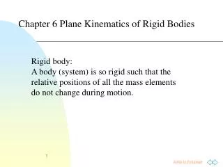
PLANE KINETICS OF RIGID BODIES. The kinetics of rigid bodies treats the relationships between the external forces acting on a body and the corresponding translational and rotational motions of the body.

E N D
The kinetics of rigid bodies treats the relationships between the external forces acting on a body and the corresponding translational and rotational motions of the body. In the kinetics of the particle, we found that two force equations of motion were required to define the plane motion of a particle whose motion has two linear components.
For the plane motion of a rigid body, an additional equation is needed to specify the state of rotation of the body. Thus, two force and one moment equations or their equivalent are required to determine the state of rigid-body plane motion.
GENERAL EQUATIONS OF MOTION In our study of Statics, a general system of forces acting on a rigid body may be replaced by a resultant force applied at a chosen point and a corresponding couple. By replacing the external forces by their equivalent force-couple system in which the resultant force acts through the mass center, we may visualize the action of the forces and the corresponding dynamic response. Dynamic response
a)Relevant free-body diagram (FBD) b) Equivalent force-couple system with resultant force applied through G c) Kinetic diagram which represents the resulting dynamic effects
PLANE MOTION EQUATIONS Figure shows a rigid body moving with plane motion in the x-y plane. The mass center G has an acceleration and the body has an angular velocity and an angular acceleration . The angular momentum about the mass center for the representative particle mi : : position vector relative to G of particle mi Velocity of particle mi g
The angular momentum about the mass center for the rigid body: is a constant property of the body and is a measure of the rotational inertia or resistance to change in rotational velocity due to the radial distribution of mass around the z-axis through G. (MASS MOMENT OF INERTIA of the body the about z-axis through G)
Analysis Procedure In the solution of force-mass-acceleration problems for the plane motion of rigid bodies, the following steps should be taken after the conditions and requirements of the problem are clearly in mind. 1) Kinematics : First, identify the class of motion and then solve any needed linear or angular accelerations which can be determined from given kinematic information. 2) Diagrams: Always draw the complete free-body diagram and kinetic diagram. 3) Apply the three equations of motion. ()
O r dm O Mass Moments of Inertia Mass moment of inertia of dm about the axis OO, dI: Total mass moment of inertia of mass m : I is always positive and its units is kg.m2.
Transfer of axes for mass moment of inertia: If the moment of inertia of a body is known about an axis passing through the mass center, it may be determined easily about any parallel axis. G d O
Mass Moments of Inertia for Some Common Geometric Shapes Thin bar Thin circular plate Thin rectangular plate
Radius of Gyration, k: The radius of gyration k of a mass m about an axis for which the moment of inertia is I is defined as Thus k is a measure of the distribution of mass of a given body about the axis in question, and its definition is analogous to the definition of the radius of gyration for area moments of inertia. The moment of inertia of a body about a particular axis is frequently indicated by specifying the mass of the body and the radius of gyration of the body about the axis. When the expressions for the radii of gyration are used, the equation becomes
TRANSLATION • a) Rectilinear Translation: FBD Kinetic Diagram w=0 a=0 Path of G F1 x “m” “m” G x F2 G d d A P A Fn P F3
PROBLEMS 1. The uniform 30-kg bar OB is secured to the accelerating frame in the 30o position from the horizontal by the hinge at O and roller at A. If the horizontal acceleration of the frame is a=20 m/s2, compute the force FA on the roller and the x- and y-components of the force supported by the pin at O.
PROBLEMS 2. The block A and attached rod have a combined mass of 60 kg and are confined to move along the 60o guide under the action of the 800 N applied force. The uniform horizontal rod has a mass of 20 kg and is welded to the block at B. Friction in the guide is negligible. Compute the bending moment M exerted by the weld on the rod at B.
SOLUTION Kinetic Diagram FBD mTax=60ax x x N 60o W=60(9.81) N FBD of rod KD of rod By m1ax=20ax Bx M W1=20(9.81) N
b) Curvilinear Translation: FBD Kinetic Diagram w=0 a=0 t F1 t “m” “m” G B F2 Path of G dB G A G dA Fn F3 n n + +
PROBLEMS 3. The parallelogram linkage shown moves in the vertical plane with the uniform 8 kg bar EF attached to the plate at E by a pin which is welded both to the plate and to the bar. A torque (not shown) is applied to link AB through its lower pin to drive the links in a clockwise direction. When q reaches 60o, the links have an angular acceleration an angular velocity of 6 rad/s2 and 3 rad/s, respectively. For this instant calculate the magnitudes of the force F and torque M supported by the pin at E.
PROBLEMS 4. The uniform 100 kg log is supported by the two cables and used as a battering ram. If the log is released from rest in the position shown, calculate the initial tension induced in each cable immediately after release and the corresponding angular acceleration a of the cables.
SOLUTION +n FBD KD +n TA TB +t +t W=100(9.81) N When it starts to move, v=0, w=0 but a≠0 * Length of thecables Themotion of thelog is curvilineartranslation. *
PROBLEMS 5. An 18 kg triangular plate is supported by cables AB and CD. When the plate is in the position shown, the angular velocity of the cables is 4 rad/s ccw. At this instant, calculate the acceleration of the mass center of the plate and the tension in each of the cables. C A 24 cm D B 60° 60° 10 cm G Answer: 20 cm 20 cm
2) FIXED-AXIS ROTATION For this motion, all points in the body describe circles about the rotation axis, and all lines of the body have the same angular velocity w and angular acceleration a. The acceleration components of the mass center in n-t coordinates: Equations of Motion * FBDKinetic Diagram **
For fixed-axis rotation, it is generally useful to apply a moment equation directly about the rotation axis O. Using transfer-of-axis relation for mass moments of inertia; For the case of rotation axis through its mass center G: FBDKinetic Diagram
PROBLEMS 6. The uniform 8 kg slender bar is hinged about a horizontal axis through O and released from rest in the horizontal position. Determine the distance b from the mass center to O which will result in an initial angular accelerationof 16 rad/s2, and find the force R on the bar at O just after release.
PROBLEMS 7. The spring is uncompressed when the uniform slender bar is in the vertical position shown. Determine the initial angular acceleration a of the bar when it is released from rest in aposition where the bar has been rotated 30o clockwise from the position shown. Neglect any sag of the spring, whose mass is negligible.
SOLUTION Unstrecthed length of the spring: When q=30o , length of the spring: When q=30o , spring force: (in compression) 30o W Fspring . +t +t 60o lspring G Ot G +n +n 60o 30o O l On
3) GENERAL PLANE MOTION The dynamics of general plane motion of a rigid body combines translation and rotation. Equations of motion: FBDKinetic Diagram In some cases, it may be more convenient to use the alternative moment relation about any point P.
PROBLEMS 8. In the mechanism shown, the flywheel has a mass of 50 kg and radius of gyration about its center of 160 mm. Uniform connecting rod AB has a mass of 10 kg. Mass of the piston B is 15 kg. Flywheel is rotating by the couple T ccw at a constant rate 50 rad/s. When q=53odetermine the angular velocity and angular acceleration of the connecting rod AB (wAB ve aAB).What are the forces transmitted by the pins at A and B? Neglect the friction. Take sin 53=0.8, cos 53=0.6.
PROBLEMS 9. Member AB is being rotated at a constant angular velocity of w = 10 rad/s in ccw direction by a torque (not seen in the figure). Rotation of AB activates the 6 kg rod BC, which causes the 3 kg gear D to move. The radius of gyration of the gear about C is 200 mm. The radius of gear D is given as r = 250 mm. For the instant represented determine the forces acting at pins B and C.
PROBLEMS 10. The unbalanced 20 kg wheel with the mass center at G has a radius of gyration about G of 202 mm. The wheel rolls down the 20o incline without slipping. In the position shown. The wheel has an angular velocity of 3 rad/s. Calculate the friction force F acting on the wheel at this position.
SOLUTION “General Motion” FBD KD y mg = x x Fs N
PROBLEMS 11. The uniform 15 kg bar is supported on the horizontal surface at A by a small roller of negligible mass. If the coefficient of kinetic friction between end B and the vertical surface is 0.30, calculate the initial acceleration of end A as the bar is released from rest in the position shown.