Wireless Network Location Verification
Wireless Network Location Verification. Presented by Wosen Agedie and Samuel Walker Mentor: Dr. Beex. Project Background.

Wireless Network Location Verification
E N D
Presentation Transcript
Wireless Network Location Verification Presented by WosenAgedie and Samuel Walker Mentor: Dr. Beex
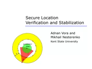
Project Background The purpose of this project is to come up with a model to accurately locate where a transmitting device is indoors where Global Positioning Systems cannot by using an indoor wireless network.
Future Applications • 9-1-1 Emergency Personnel who need to locate a victim trapped in a building • Parents who need to locate their child in a crowded, large building (mall, museum, etc.) 3. Locate lost personal items (cell phone, keys, etc.)
Gigabit Ethernet: interface between USRP2 (installed in the ceiling) and the processing platform. • 12 nodes per floor for a total of 48 wireless nodes, each node is connected to a server
Equipment/Software Used • Signal Function Generator • Cone-shaped antenna • USRP2 w/ WBX Daughterboard • Power Meter • NX Client • MATLAB • Microsoft Excel
USRP2 WBX Daughterboard
Universal Software Radio Peripheral (USRP) • Provide hardware platform for software radio • It connects with the host computer using USB ot Gigabit Ethernet • Usually used with GNU radio software tool. • Has a motherboard wich provide the folowing subsystem: FPGA ( field-programmable gate array) ADC (analog-to-digital converter ) DAC (digital-to-analog converter ) clock generation
Calibration Method Rx Calibration Diagram USRP USRP Signal Generator Laptop Laptop Power Meter Tx Calibration Diagram
Testing Results First Floor Second Floor
Localization Model When each power level from nodes are plotted in order from 1-48: • We can easily spot the highest peak between the four floors of the building • The floor with the highest peak is where the transmitting device is located • The nodes with the highest power levels shows the vicinity of where the transmitter is located
Things Learned • Transmitter power level is very important in order to locate a transmitter. The lower the power level, the harder it is accurately pinpoint the vicinity of the transmitter. • The position and number of nodes used to locate a transmitter is very important. The more nodes that are utilized, the more accurate the transmitter’s location.
Future Work • Find the minimum power level required to accurately locate a transmitter • Find the minimum number of nodes and the distances between each one to accurately locate a transmitter
Mentors and References • Dr. Beexand Tamoghna Roy (Mentors) • Dan Depoy (CORNET Administrator) • Dr. Dietrich (Hardware and Supplies) “Designing and Deploying a Building-Wide Cognitive Radio Network Testbed” Authors: Timothy R. Newman, S. M. ShajedulHasan, Daniel DePoy, Tamal Bose, and Jeffrey H. Reed, Virginia Tech Published by IEEE Communications Magazine